Hi,
Please could you help me with wiring of the new Airbot Omnibus F4 V6 ? I’m need connect Jeti Duplex Rx to the board via PPM, and still not luck. I can not find correct pins where PPM should be soldered. I try solder to the 5V, GND and SBUS pin, set rx type to PPM, but still not luck. I’m using iNAV 2.0. Other perefieries like GPS, MAG, CAM works well.
Hi, Thank for your tip, I flash betaflight omnibusf4fw target,
I remaped PPM to the PC7 (=SBUS pin on board), and PPM works fine.
But PC7 is connected to the Serial_Rx 6 which is used for GPS on the, in case I use PC7 for PPM, there is question can I remap GPS pins to use on board pins marked as GPS ?
Update: Ok, I remaped some pins and now it seem it’s works
PPM solder to to S-Port (TX1) and map PPM to PA9)
Now I succesfully connected PPM, but I can not solve MAG.
My GPS+MAG works well with this board with iNAV and on other boards, there are pullup resistors, on F4 V6 with betaflight I use pins SCL/SDA (same as with iNav whe is works)
, map resource to SDA PB9 and SCL to PB8 but not luck
Any idea please ?
used commands:
resource ESCSERIAL none
resource CAMERA_CONTROL none
resource I2C_SCL 2 B08
resource I2C_SDA 2 B09
set mag_i2c_device = 2
B08 and B09 are free and i see no i2c on your current resource.
is the above resource still betaflight or inav?
if you changed resources in betaflight when you reflash ivav changes made in betaflight will be lost.
Hi Dale, sorry for confusing, it’s Betaflight, I moved to BF because I don’t hawe experience to define and compile iNav with PPM support.
There is I2C on pin B09 and B08 inn “resource” but the I2C is missing in “resource list”, I’m realy don’t know why and what does it mean
I know, there is error with bus number, this boeard use bus number 1 (no 2), (thanks Andrew for help), but with bus 1 i get same situation.
thanks for any help.
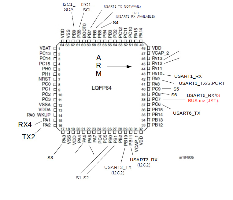
I did not get time to look at this, but I previously mapped the most important as shown in the figure below (It’s been some weeks since I did this but it should be correct). I am not familiar with PPM (particularly not with V6). Did you get it working with the current config in betaflight? I can’t see the resources. Also, PPM on this board may lead to timer collisions with the servo/motor assignments, so probably need new firmware build.
On the positive side, you may get away with the issue with the JST GPS connector on UART6 vs the inverted sbus pin which is also on serial 6, rendering the JST not usable if using sbus (not sure what the manufacturers rationale for this is). From the figure you can see that uart1 rx is available also from the LED pin.
Hi Andrew,
Thanks, yes in BF PPM worsk, with
resource PPM none
resource SERIAL_TX 1 none
resource PPM 1 A09
The resources listed above is after reset when I tried connect MAG.
I send question to Jetimodel (RX manufacture) about possibility to connect th RX with ExBus or SBUS what should be better way …