Mr Alex cam you explaιne something else to me please. According to the connection diagram here, Omnibus F4 V6 Flight Controller Guide the sbus cable from my receiver goes to sbus pad which is UART6, If I want to connect my gps module on 6 pin JST-SH 1.0 connector, as I can see, goes on RX6 and TX6 which is UART6 too. Does this mean I will have a conflict as I have to enable two fuctions on the same UART? Do I miss something here?
Yes good point, I thought it will be more clear building if I was able to use the 6 pin JST-SH 1.0 connector. But anyway I guess this is the only one solution at the end. Thank you.
Finally as I received my OMNIBUS F4 V6 and start to test it, I fegureout that I cant connect gps to UART 3 because when i do that, magnetometer does not work. The problem remains.I can not have both receiver and gps working at the same time. When I have sbus enable , can not
have gps at the same time. It seems to share the same uart (uart6 ) I can’t find a solution, Any help?
Can you share how you have connected everything also also how you have setup the ports within betaflight? Can you also let me know what firmware you are running and that you have loaded the omnibusF4FW firmware onto your board?
You can use both UART3 (GPS) and I2C (compass) so I am pretty certain you have either connected something wrong or dont have the correct settings in the firmware.
I am using inav not betaflight, with this firmware: inav_2.0.0_OMNIBUSF4_V6_extends_FIREWORKSV2.hex.zip
providing in this topic: I2c magnetometer not working on Omnibus f4 v6, as gps and mag are working but sbus does not.
Btw, I will post my tries in details as soon as possible.
Thank you in advance.
Hi,
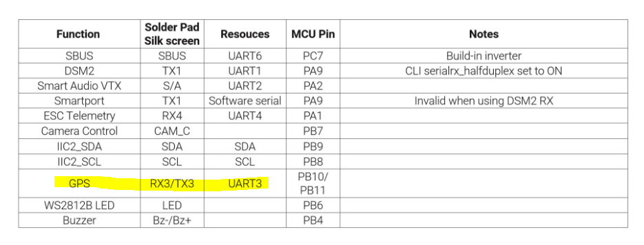
The 6 pin JST RX,TX is wired to UART6 (PC6 and PC7). I made some notes on this in an earlier post, including a diagram. One of the reasons for all the confusion is the erroneous pinout description that is found online. If you want to use the hex I earlier compiled for INAV you could use UART3 for GPS (sbus on USART6). This means that you cannot use the JST pin, but solder to RX3/TX3.
So, those are my tries:
First configuration
GPS TX to RX3 FC!
GPS RX to TX3 FC
GRS SDA to SDA FC
GPS SCL to SCL FC
SBUS receiver to SBUS FC
SPORT receiver to TX1 FC
GPS Enabled, sbus enabled, can,t choose magnetometer, after save and reboot, it changes to NONE.
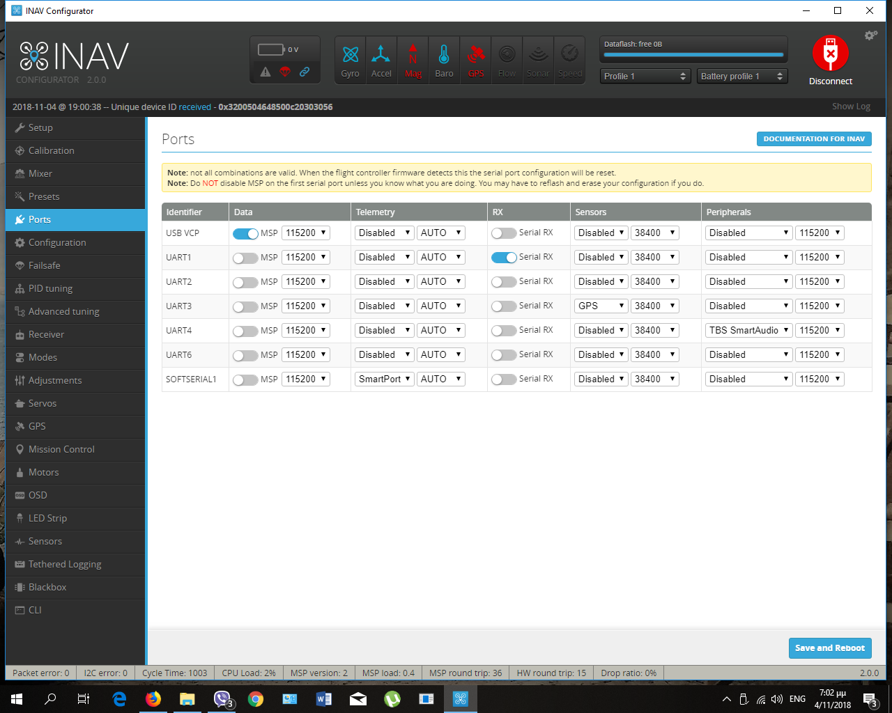
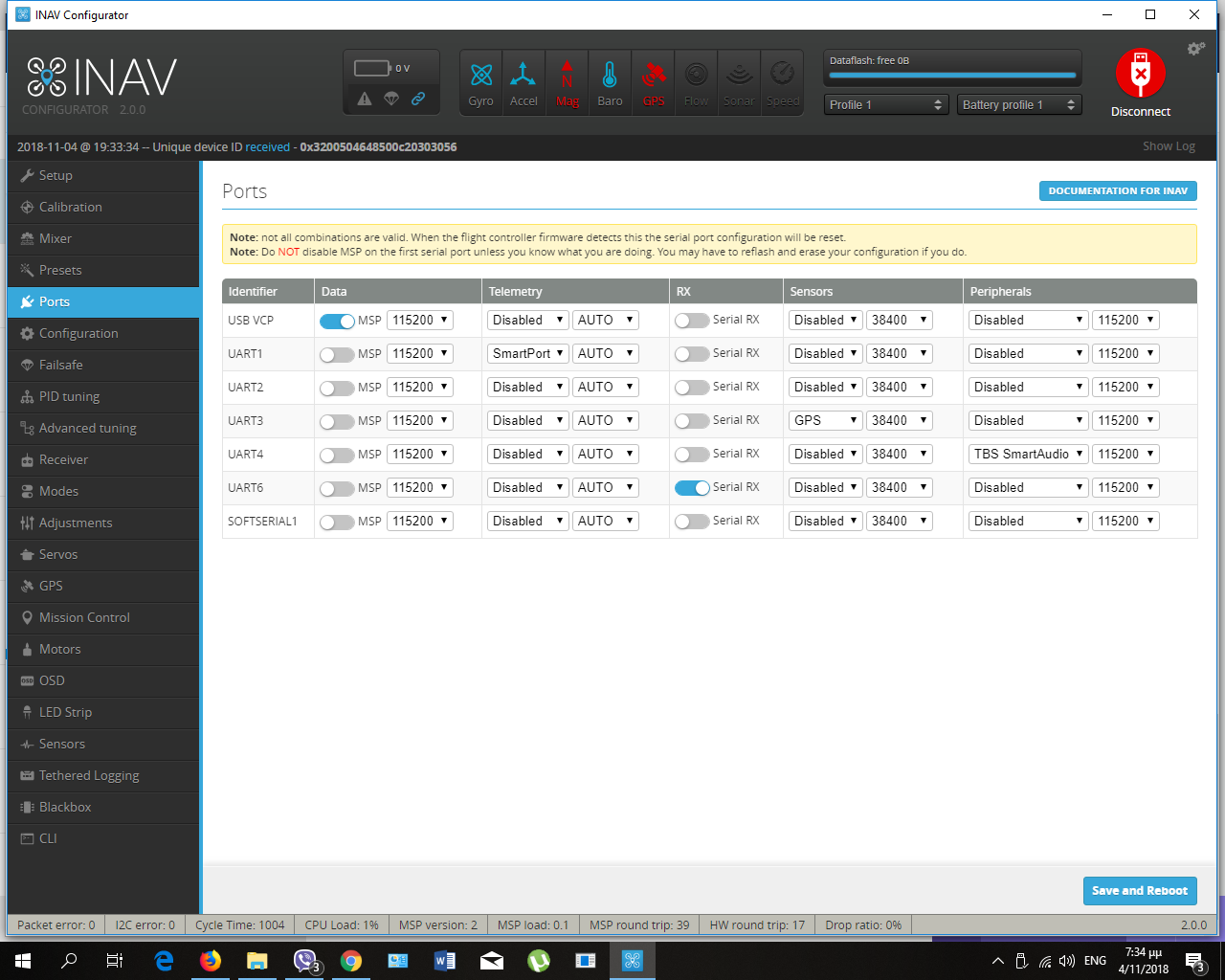
Ports screenshot:
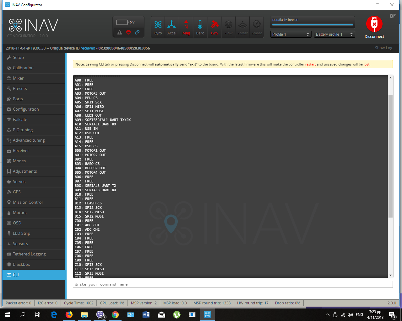
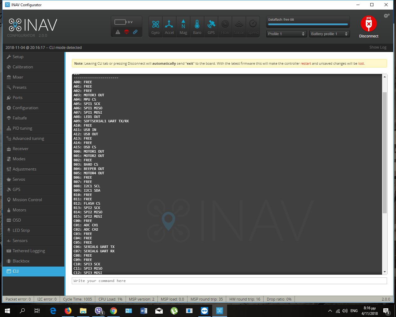
Resource list:
Results:
no gps
no mag
no telemetry
no sbus
Changing the ports, I have the followings:
Resource list

Results
no gps
no mag
yes telemetry
yes sbus.
Second configuration:
GPS TX to RX6 FC
GPS RX to TX6 FC
GPS SDA to SDA FC
GPS SCL to SCL FC
SBUS to SBUS FC
SPORT to SOFTSERIAL1
GPS Enabled, sbus enabled, MAG HMC5883.
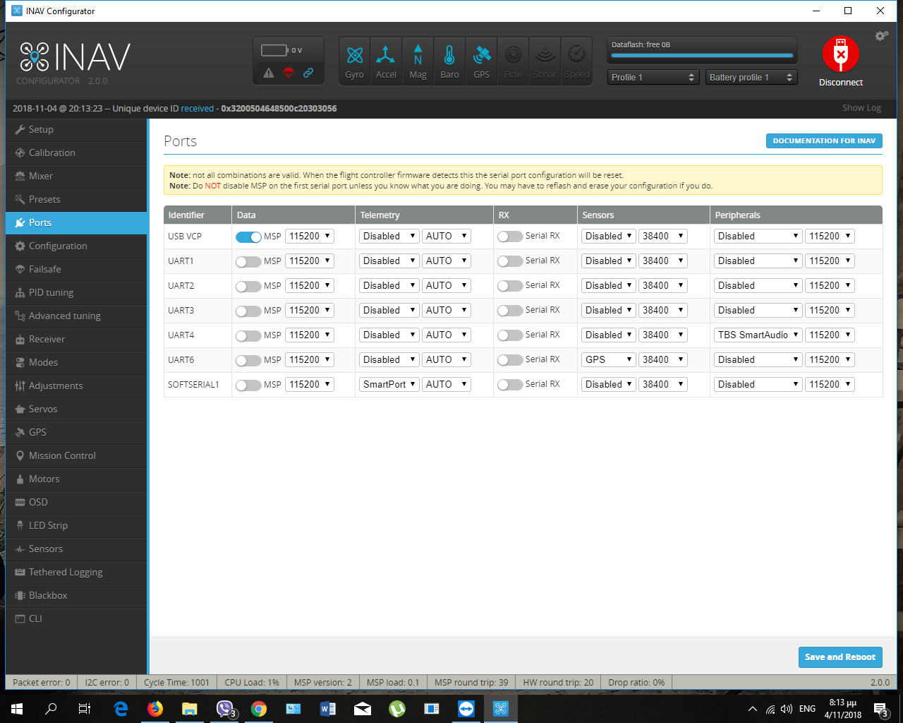
Resource list:
Results:
yes gps
yes mag
no sbus (I didn’t choose any port)
no telemetry
Now, If I choose the UART 1 as sbus I take this in receiver tab:
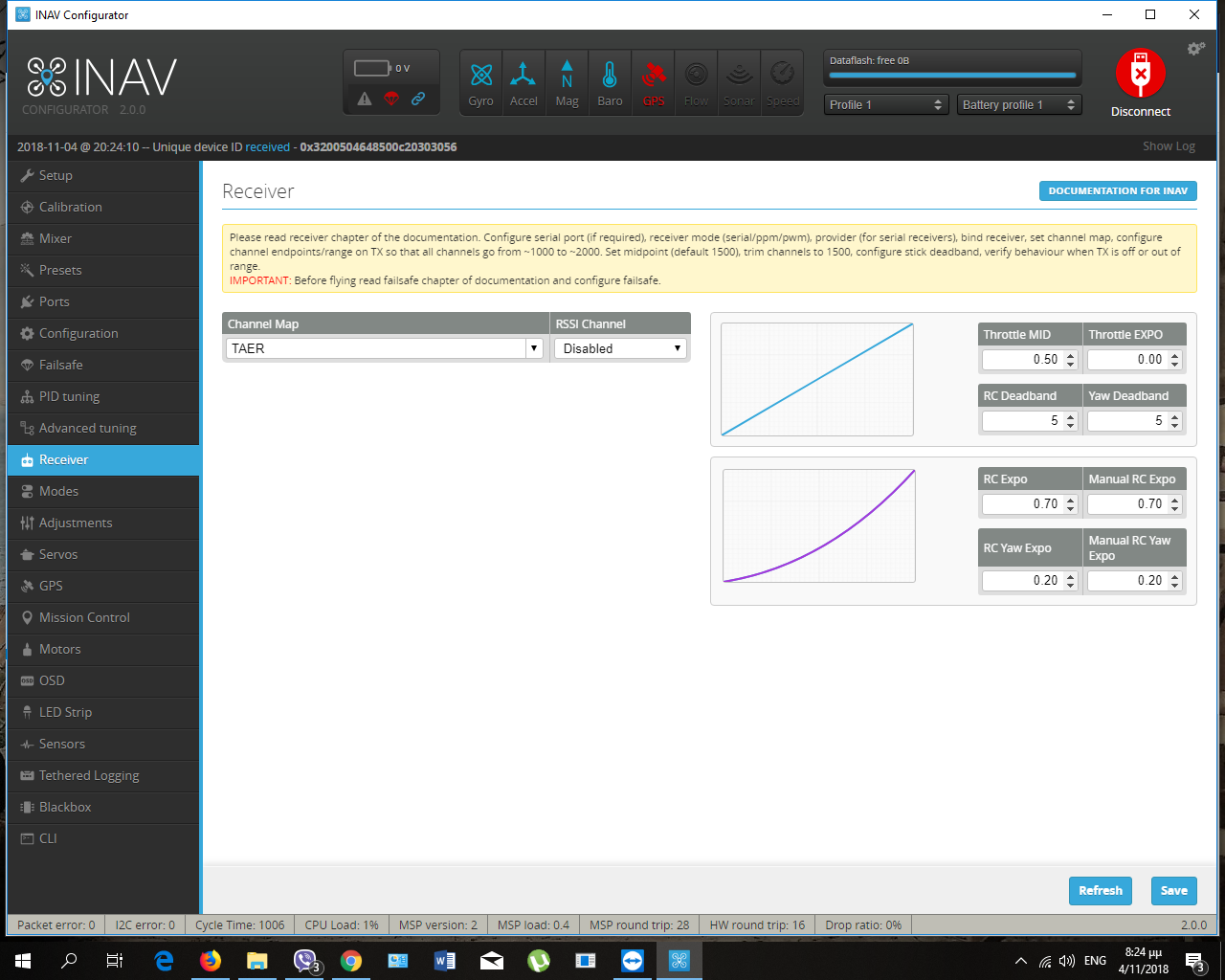
… and gps goes off.
Where is the wrong?
Thank you in advance for your time.
silly question, at the bottom you have gps and mag but no receiver, which was connected to sbus pad but no port selected. then you say you selected sbus on uart1. now heres the silly question did you leave the receiver on sbus pad or solder it to the uart1 pad?
It looks like the Inav firmware you have on your FC deffinately allocated GPS to UART6… so my suggestion would to use SBUS on UART 6 and then use softserial UART for GPS maybe, or connect your GPS to another UART port like UART 3
The solution finally is here
This topic was automatically closed 3 days after the last reply. New replies are no longer allowed.