Help Flashing an Unknown F3 Board with NO Boot pads (now identified as a Teeny 1S F3)

I have an F3 AIO type board that I had no idea how to put into DFU mode. Now, the logic of not having boot pins, pads, and buttons escapes me. I mean, I know the newest trend is for doing many things in the CLI is great, like calibrating esc’s, configing the OSD, but there is always a need for manual options. That said, logic dictates that there must be some sort of way to re install the drivers to get this thing to communicate, if you mess up. That is being stated because logic dictates that when this thing was manufactured, the chip was most likely not manufactured with the drivers already installed. Soooo here I am.

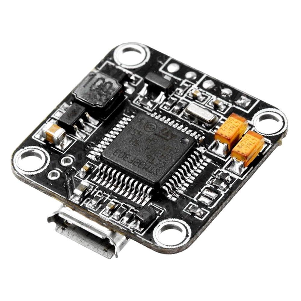
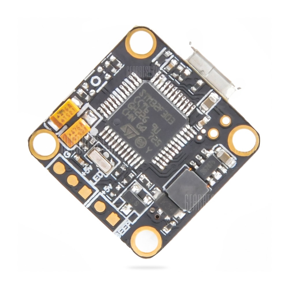
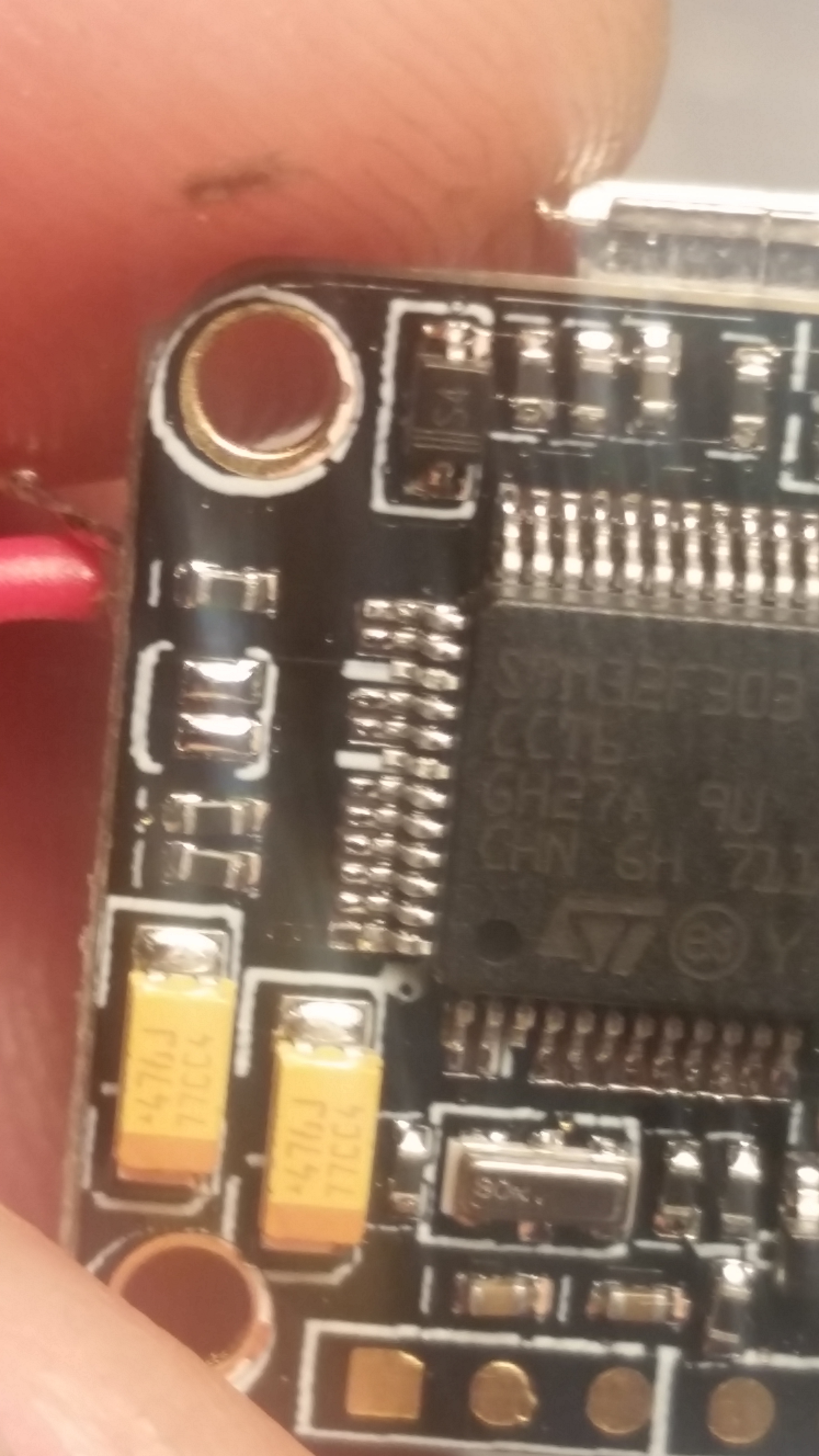
First of all, I have no idea of the base name for this thing. It is a 16X16 F3 with an OSD, and a couple of ports, so if anyone can ID it, it would be helpful. I usually type the name of a board into google, and I come up with the answers after I dig for awhile.

Now, the outfit I purchased it from, is a great little outfit on ebay called USA Quadcopters, out of Texas. I have asked a few questions, and received some answers, but I need to find more answers.
They did give me an answer on how to get it into DFU mode to update the firmware by pluging it in, and un pluging it a few times, but it only works if things are communicating.
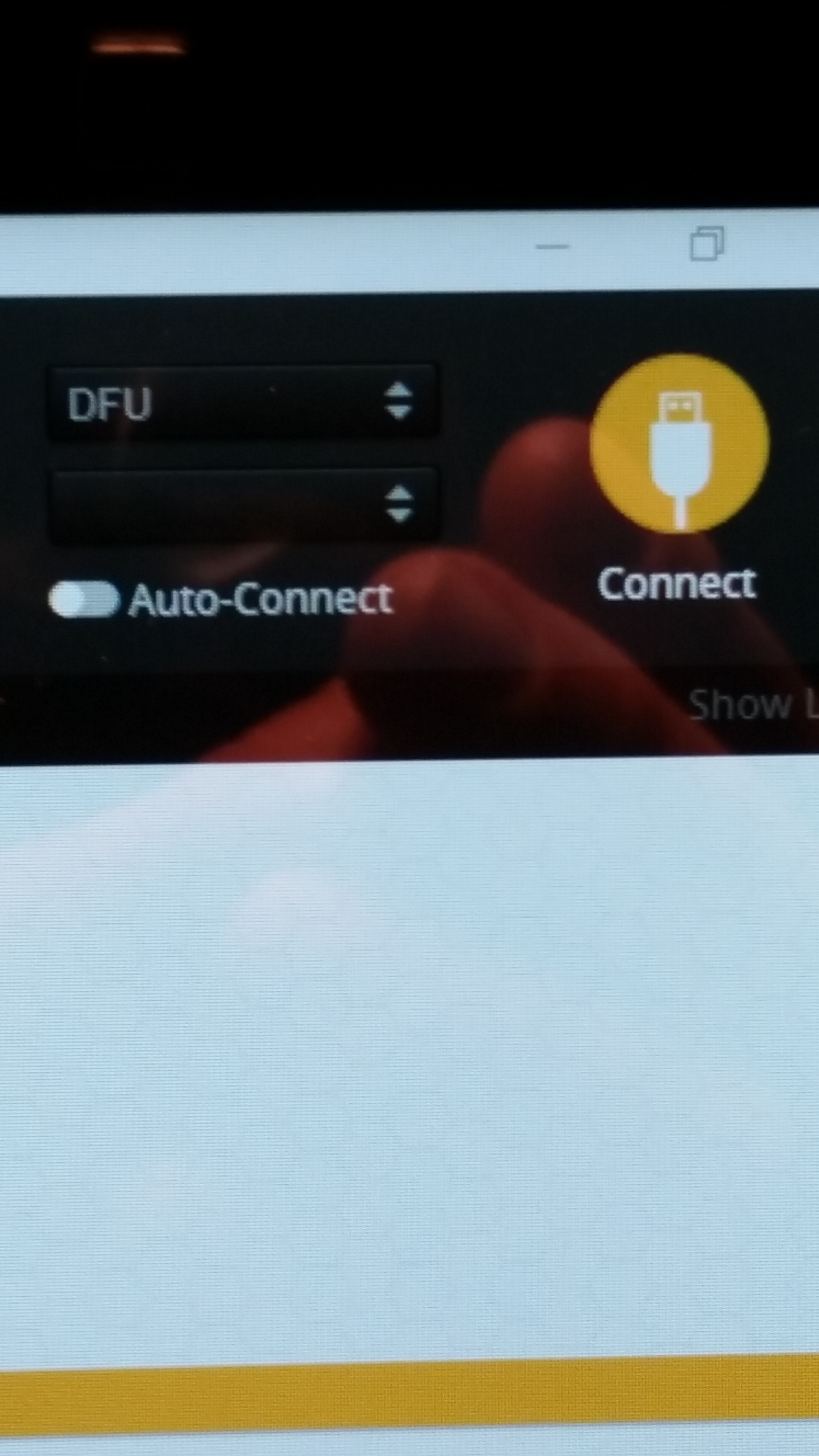
On the firmware flashing page of Betaflight, you will see a DFU where the Com ports are shown when doing this, and I did try typing “BL” in the CLI which did not work when it was communicating.

BUT, when I managed to get it into DFU mode, and was trying to install BF 3.5, I loaded the SP Racing Hex by mistake, instead of the Omnibus Hex, and now I am completely locked out.
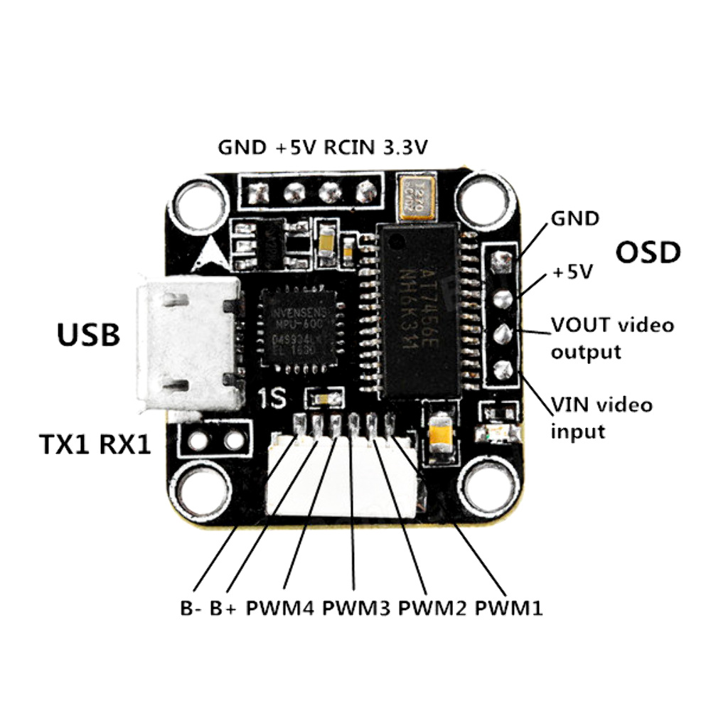
I have tried everything, including connecting to it with an FTDI through RX, and TX 1, but still cannot get the drivers in.

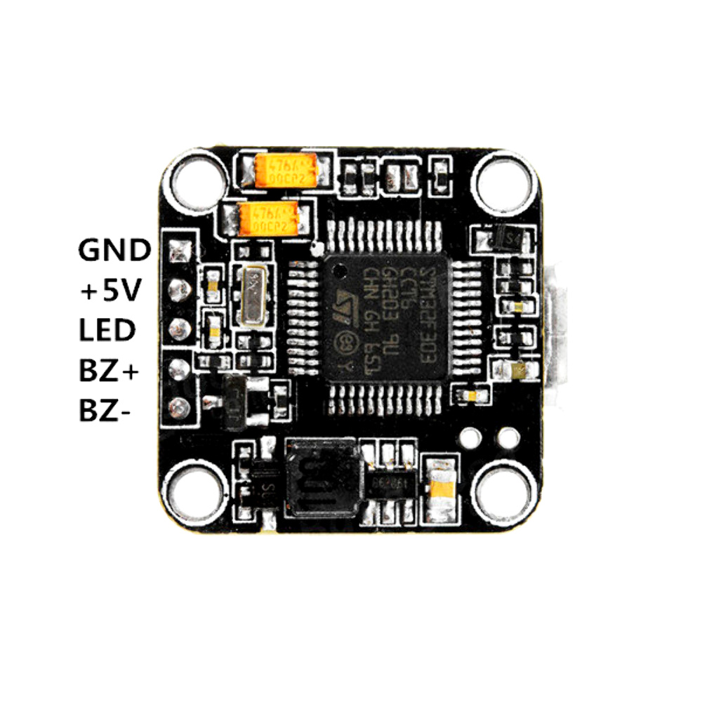
So if there is anyone here that can assist me it would be helpful. I will upload close up pics.
PS, I am suspecting that the B+, and B- are the boot pads, but need opinions, as I do not want to waste the money spent, and SMOKE this thing.
Thanks
Ted

so when you say locked out. can you not get CLI up?
and the Batt +ve and -ve pins are what they say NOT BOOT PINS.

Hello Dale,
Yes can’t get into the CLI. I am suspecting that maybe the Tx1 and Rx1 may need to be bridged. I say this because as I have been pondering it today, the spacing between the pins are not the standard dupont spacing. They have the same spacing as the Frsky binding pins. I soldered the smaller pins to the Tx1 and Rx1 to try to communicate with an FTDI, which I can, as it shows in device manager, but the same locked out condition is there, with basically a boot loader error.
Thnx
This is how I connected through tx an rx 1

On the F3 board the USB and UART1 are the same so that is why you are getting the same results.
If on betaflight and you plug FC in does it see a com port ( does your computer make the youve just plugged something in noise).
Just flashing the wrong firmware should not have BROKED the FC.
Some FC dont have boot pins which is why very important to flash correctly.
From what you are saying id say FC toast unless someone else as any ideas.
FYI next time you want to update firmware with no boot pins, just go into BF with the firmware on it go direct to CLI and type dfu and save it will reboot in dfu mode.
Save messing around plugging and unplugging (which doesent help) to get dfu mode .

Yeah, I thought I would get the same result when I used the FTDI, but thought it was worth a try. I do not get the something is connected sound in a Win 10, and a Win 7 laptop. The Impulse RC driver fixer does not work either, nor does Zadig, and the ST Flash loader. Nothing works. Well, if there are no boot pins, how did the maker get the drivers on there in the first place? That’s the Dilemma.

If they did it then, then why can I not do it now? I mean, it was only $24, but this is just another learning curve problem to learn.

We all have smoked, and messed up alot of equipment in the learning process, and when presented with something like this, it makes me tenacious at finding a solution.

Some FC’s use trace holes that are right next to the mini USB for the boot pins. This board has that. Its the TX/Rx 1 pins. I haven’t bridged them yet for fear of smoking it, but that will be my last solution before I Bin it.

I was also told that it could be a CP210 driver problem why the Impulse driver fixer does not work. I was told to uninstall Zadig, STM flash loader, CP210, then re install CP210

Found out what it is its a TeenyF3 Omni F3 Pro Flight Controller STM32F303CCT6
I tried to bridge the Rx Tx to no avail, and re installed the drivers on my computer. Nothing. No can do, so i guess it is bricked…

sounds about right, and you are so correct about the smoking learning curve. better to do on cheap stuff though.

Thanks, BUT, and a big but it is…

I have not given up. There is no better time to solve a problem, then the time you don’t care anymore if you smoke something or not. Lol

From JC’s videos (RIP), I seem to have gleaned some info that may work.

From his videos on how to replace a processor he showed a PDF of the actual layout of an F4 processor. I noticed that there are pins on the chip, that are the boot pins, which basically go to a trace on a board with a button, pads, whatever.

So, I may have answered my own question, on how to get it into boot loader mode for initial programming, and flashing.

I say this because as I was pondering this at work, I came across a similar board which uses an F303, and has boot pins right next to the processor, with traces that look like they go right to the pins on the chip.
So I am off to the races, and now, after putting on my super magnifying glasses, I found the boot pads on my board. This is when I was told that it had none, so I guess I didnt look hard enough.

Now, if you look close, you can see that the pads are directly traced to the pins.
I am so glad I did not have to do a trial and error to see which pins on the chip I had to short. They are designated by the screening on the PC board pointing to directly where they go.

I am going to find the EXACT pinout diagram for this processor, to see what pins need to be grounded together to enter the boot loader mode in hopes it will work for other boards. I know one is boot/0

I will do an update when I get new firmware uploaded, fingers crossed…

Now, I am going to do a Youtube video on this in Honor of JC, who still helps people from the Grave. I do not know the story of how he passed, I just know from reading the comments on his videos, that he did.
RIP

Hope it goes well, BUT if windows can’t see see it there’s nothing there to boot!

scratch that I haven’t tried it yet

Success!!!

Full chip erase, no re boot sequence did it.

The last pic is the absolute best way I have found to bridge those little pads…

Take a small carbon rod, and mash the end a few times with a small hammer into something that looks like a small paint brush. Bridge the pads and connect. I have seen people use razor blades, screw drivers wire, etc. This works the best without scarring the little traces connected to the board

It’s a little carbon brush…

So problem solved, but only because I found the boot pads. I am still going to do an update once I study some STM F303 pinout diagrams.
Stay tuned…

1 Like

Well done for sticking it out and searching for a solution.
Then sharing the solution to save others.

Doomed FPV What a great screen name…

Sometimes I feel doomed at doing this, but have learned to stick it out. There are answers out there, people just need to stick with it, and think, and search the forums for answers.

I have now come to the conclusion that to omit the boot pads is stupid. I thought it was this way on this board, but I was wrong because of a simple oversight…

I did not look hard enough, and check it for myself.

I have also come to the conclusion that, unless you see the magic white smoke, all is not lost. And even then, if you can identify what smoked, most likely it could be replaced if you really wanted to.

SMT electronics has come a long way since I saw the very first Shuttle launch. I was once told that the Shuttle used the equivalent of a Commodore 64 computer of the day for flight control. Like I said , a long way.

This is what I am building around the FC in this post…

1 Like

Patients is a virtue, you have plenty my son.
still surprised you got working if windows didnt detect it even being plugged in!

Thanks to you Dale, I did not cross the b+ and the b- pins. That would have resulted in a resonating Dammit !!!
What was I thinking…
$24 bucks is $24 bucks…
Also, Once plugged in, I noticed that being I did get BF 3.5 on it, it now connects via a VCP connection, and I am no entirely sure, but I think is shared a connection with UART 1 before the update. I think…
The next thing I’m going to do to it is hook up a mini gps to it.
I have the plans for the swift above, and am about to do a whole series of videos on the whole process of building, set up, tuning, and first flights flying it.
It is of my opinion that the only way we are going to continue to enjoy this hobby, is to go to smaller craft, due to what is happening near controlled airspace. The eye of Soron is watching civil, and hobby drones.