Hi
Venturing for the first time into the 4 in 1 ESC world and had a question regarding the wiring.
I’ve purchased the Cicada 20A 4 in 1 ESC and a Diatone F3 V3 FC with integrated PDB from Unmannedtech. My plan was for the battery pack voltage to go to the 4 in 1 first and then simply spur off from there to the battery pads of the FC. In principal that should be fine, right? I don’t need current sensing in my setup…
The other thing is that the pre-soldered battery pigtail leads (to which i’d attach an XT60 connector) on the 4 in 1, are very flimsy looking 16AWG cables. Running 4S i’d prefer atleast 14AWG or even 12AWG cables. Unfortunately the pads on the 4 in 1 for batt power are so small i’m tempted to wire up the battery lead to the much bigger pads on the FC with 12AWG cable and spur off from there down to the 4 in 1 with the existing 16AWG cable. Is that fine?
Here are links to the components i’m talking about:
https://www.unmannedtechshop.co.uk/d-link-v3-f3-flight-controller-with-pdb/
https://www.unmannedtechshop.co.uk/cicada-20a-blheli_s-bb2-4in1-esc-with-bec/
Many thanks for your help!
First of all:
Your idea seems fine to me…
if you know, what you do, you can do that…
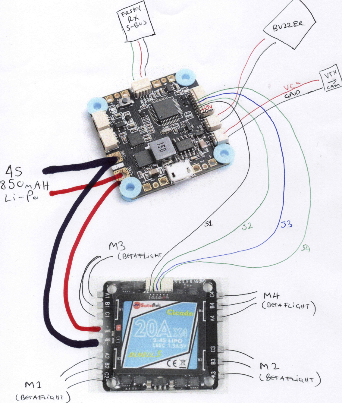
BUT: If you arent sure, i would wire the power like this (
)
I know, that this isnt right with the Colors, but i think you get the Idea…
I hope i dont misunderstoud you 
If the poles are wrong : Im sorry 
1 Like
Hi Luca
Many thanks for taking the time to draw out a schematic. That’s great! It is what I had in mind. I will though, as I mentioned before change the power cables on the 4 in 1 to something thicker. Or is it really necessary?
No Problem 
It is not necessary, to chnage the cables to thicker ones…
Maybe watch this Video…
https://www.youtube.com/watch?v=Avp8MurmeEY
TIMES:
Soldering the power supply to the 4 in 1 ESC : 18:15 - 19:10
Soldering the Signal-Cables to the Flight Controller: 26:11 - 27:40
Just handle it, like the PDB is the FC… very easy
Great diagram, however the only issue is that if you plan to use the current sensor on the dlink board you need to wire it slightly differently as in that diagram the ESC current will not necessarily pass through the the current sensor.
I am on my phone right now so can make a diagram, but if you need help just let me know. But essentially you need to make sure you make sure the current flows through the current sensor and can bypass it as in the diagram.
Thanks Alex. I am aware that to have current sensing i’d have to wire the battery positive through the shunt resistor on the FC. I assume the current sensing is purely for informative/telemetry purposes? It doesn’t affect anything else does it? Telemetry-wise I only ever look at voltage to be honest…
Hi all
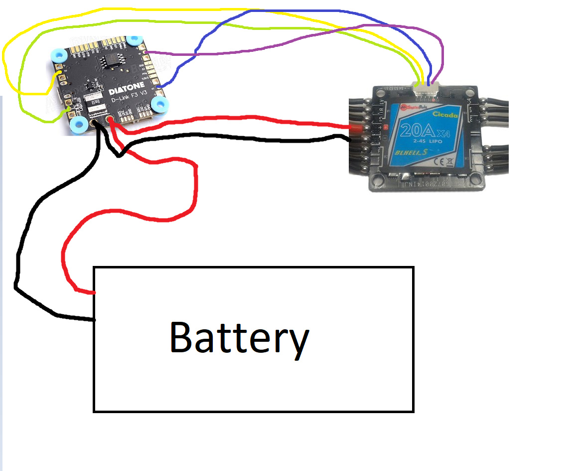
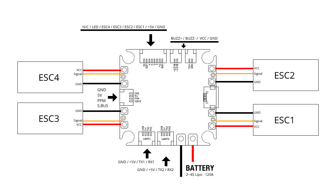
Got all the components together and wired it together in the following way making use of the JST/Molex connector port on the Diatone FC for the signal cables:
- Checked with a multimeter that nothing was bridged
- All polarities were correct
- Removed the 5V and GND cable from the JST plugs between the 4 in 1 and the FC as the FC is powered by the battery
Plugged in a 4S Li-Po, heard the ESC start up tune…and then…magic smoke appeared from the 4 in 1. Immediately unplugged…
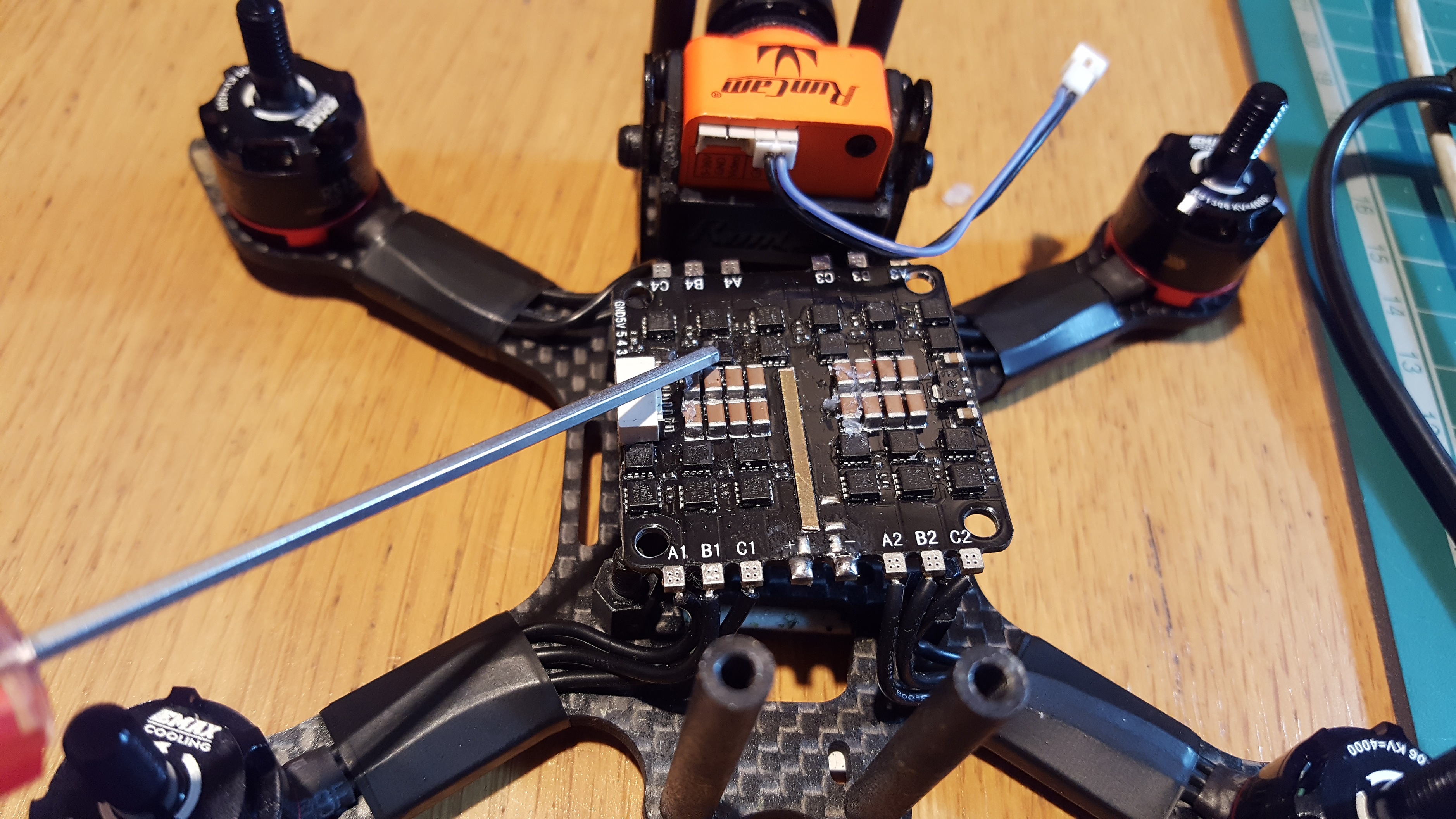
Identified the smoke coming from a burnt Mosfet? (correct me if i’m wrong!) See below:
- Isolated the 4 in 1 from the FC and powered the FC.
- All working, Runcam Mini FPV Cam, Eachine vTX (checked image on my goggles).
- Thankfully, nothing else so far has blown…
So what happened to the 4 in 1??
Thanks for your help
That is strange indeed, so it just smoked after you plugged in the battery?  You didn’t even start running the motors?
Is there any reason why you connected your ESC to the pwm output I stead of the dedicated ESC output? I can’t remember off hand if they are the same as esc1-4 connectors on the fc? 
Also what ESC mode did you have selected in betaflight and in blheli suite for the ESC?
Hi Alex
Yes, simply plugged in the Li-Po and half way through the ESC start up chime I heard a pop and a fairly large plume of smoke.
My understanding is that using the provided cable (note gnd and positive cables removed):
One can output the ESC signal cables from the 4in1 to the molex on the FC as shown:
The idea was to create a tidier build avoiding having to solder signal wires from the 4 in 1 to their corresponding pads on the FC.
Is this wrong?
ESC’s were in OneShot 125 and I hadn’t got round to BLHeli Suite (hoping to use Damped Light)
Thanks
No that should of been fine as far as I am aware.
The only other guess is that either your battery was more than 4S, or ithad the connector the wrong way (reverse polarity)… but in your case I think maybe the ESC was faulty form the factory? Did you order it from us? If so please send an email with the order number and link to this thread and we will get it sorted.
.