In this guide we will show you how to go about setting up the racing timing transponder on your seriously pro SP racing F3 mini flight controller.
Solder the LED’s
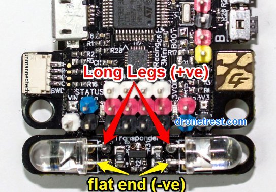
The first thing to do is to solder the IR LED’s to the two sides of the transponder. Please take care to solder the LED’s with the correct polarity. The negative pin is on the same side as the flat region on the LED, or the shorter wire
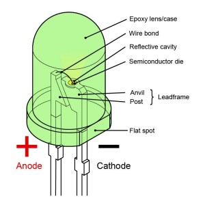
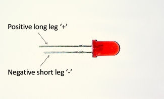
Another way to think about it is to solder the LONG wire of the LED goes in the SQUARE hole (+ve). The SHORT wire of the LED goes in the ROUND hole (-ve) on the flight controller.
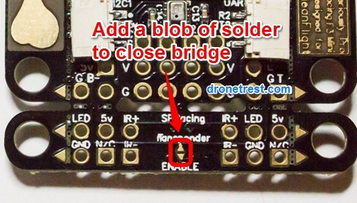
Solder the Transponder Bridge
Now you need to solder the transponder bridge pads to enable the transponder on your flight controller. This is done with a blob of solder to create a connection between the two pads. Please note that you cannot use any RGB LED’s such as the WS2812 LED strip if you enable the transponder.
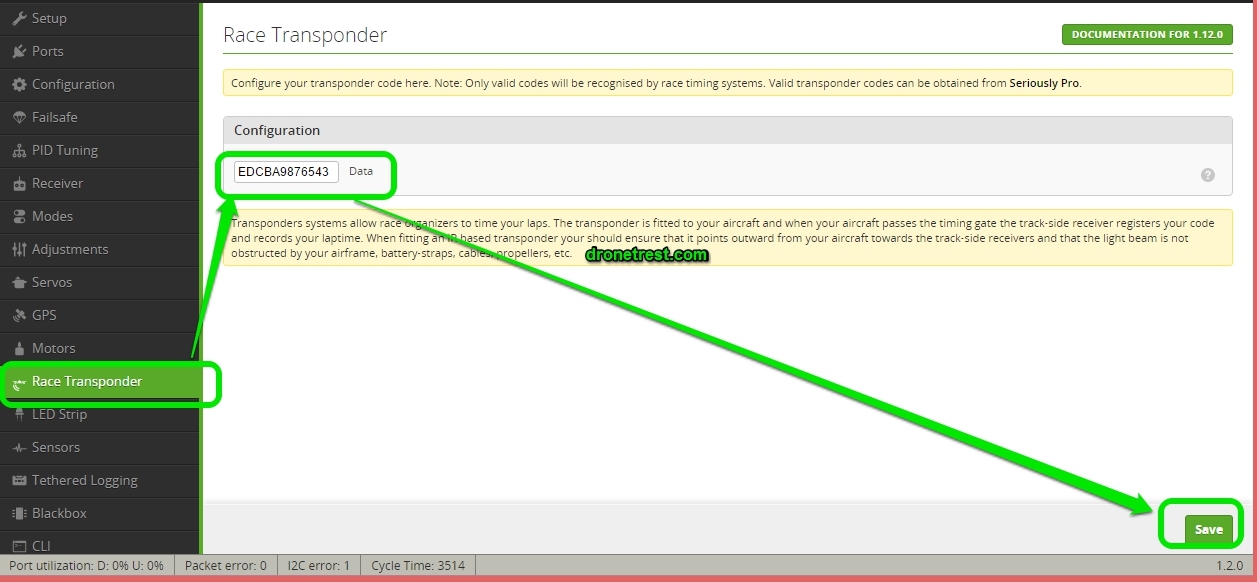
Enable in cleanflight
The final step is to enable your transponder within cleanflight. To do this you simply need to connect your board and go to the transponder tab in the software. If you dont see this option please make sure that you have the latest version of the cleanflight GUI running in your Chrome browser.
You will receive a QR code with your SPracing flight controller with a QR code which will take you to a page where you can register and download your transmitter code to enable it.
 . To the flat side/shorted leg of the LED goes to the IR- pin, and the round side/longer leg of the LED goes to the IR+ pin.

