If you have purchased a version of our brushless gimbal controllers that use alexmos simpleBGC that you cant update (due to special bootloader) then you can always replace it with the open source brushless gimbal software which you can find here
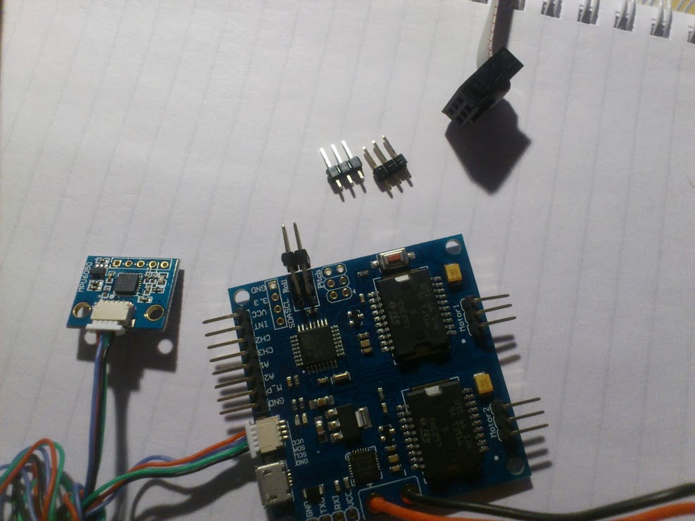
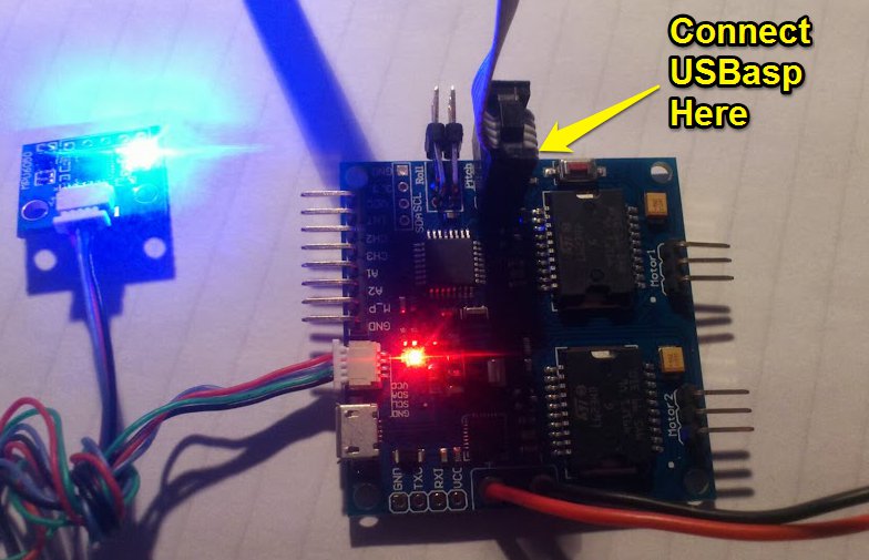
Connect the USBasp board to the brushless gimbal controller as shown below. You can use some spare headers so you dont need to solder pins onto the board. You might need to hold it in place while burning the bootloader so be careful!
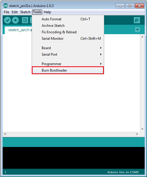
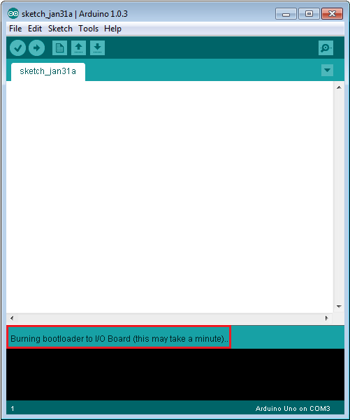
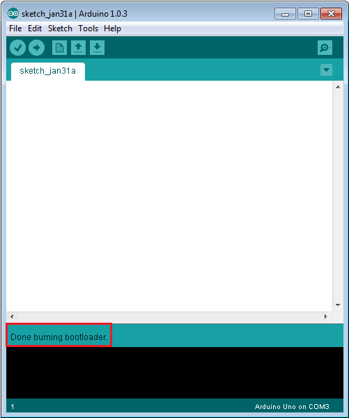
During the burning progress, the arduino software will display a message near the bottom. Be patient as this process can take a long time (up to 5 minutes)
Now the new bootloader has been burned, you can now proceed to open the brushless gimbal firmware (_BruGi.ino) and upload it as a regular arduino sketch!
Thanks, This guide is what I’ve been looking for. I have that exact same board, can you provide the pin layout so I can make sure my programmer is connected right. Thanks
I dont have it with me right now so I cant remember what the pinout is.exactly but it uses the 6 pin connector. Just make sure that your cable for the USBasp is connected as shown in the images above, where the little tab on the ISP connector should point away from the RC pins (or towards the button). If you connect it the wrong way, the board will not get any power,
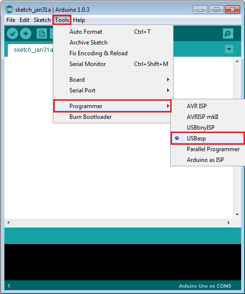
greetings do i need to place in the adruino software what tipe of board before i do the bootloader, one kwestion how do i flash the board for firmware update i have tha same board displayed in the picture.
i hope you could help,
her good afternoon 'm not managing to make the bootloader always apaerece avrdude this message : warning : can not set sck period . please check for USBASP firmware update .
avrdude : error: programm enable : target does not answer. 1
avrdude : initialization failed , rc = -1
Double check connections and try again , or use -F to override
this check .
my basecam 2 is a gimbal axis.
wanted to re- use but not this easy
Unfortunately it will not be very easy with that board, as it seems that the ISP pins dont have any headers. The only way you could do this is to connect the 6 pins from the USBasp directly to the required pins on the main micro-controller chip which is rather delicate work. If you find that your board is no longer working it might be best to try contact the shop you purchased from as they should be able to help you resolve it.
I have the same board and mine came tottaly bricked.
However i’ve managed to burn the bootloader with and Anrduino Uno as ISP. I had to solder some pins in the board also, but in the end it all worked.
Hi ,well done, my usbasp connector has 10 pins , so it would be nice to have the pinout description of the board…
Is there a connection between the mini connector of the module and the pins SDA,SCL,Vin,GND on the PCB?Because my mini connector does not seems to work anymore.