Hello, so I’ve built this drone using some cheap parts from amazon. I’m not looking to anything extravagant, the drone has a certain purpose. But i have some Hobbypower SimonK 30A ESC connected to a Hobbymate PDB and the PDB is connected to an iFlight SucceX-E F405 FC. Also the motors are made by Crazepony and my transmitter is a FlySky FS-i6X with an FS-iA6B 6 channel receiver. After everything has been put together, it works! The only issue I’m having is that all of my motor controls are separated on my transmitter. This would be fine if i had an three hands but unfortunately I don’t (I mean think of the possibilities). All i want is to raise the throttle and all 4 of my motors spin instead of have to lift the throttle push it to the left and flip switches. Is this a calibration issue with my ESC’s or do I have to change some settings on my transmitter?
Normally the FC does this for you.
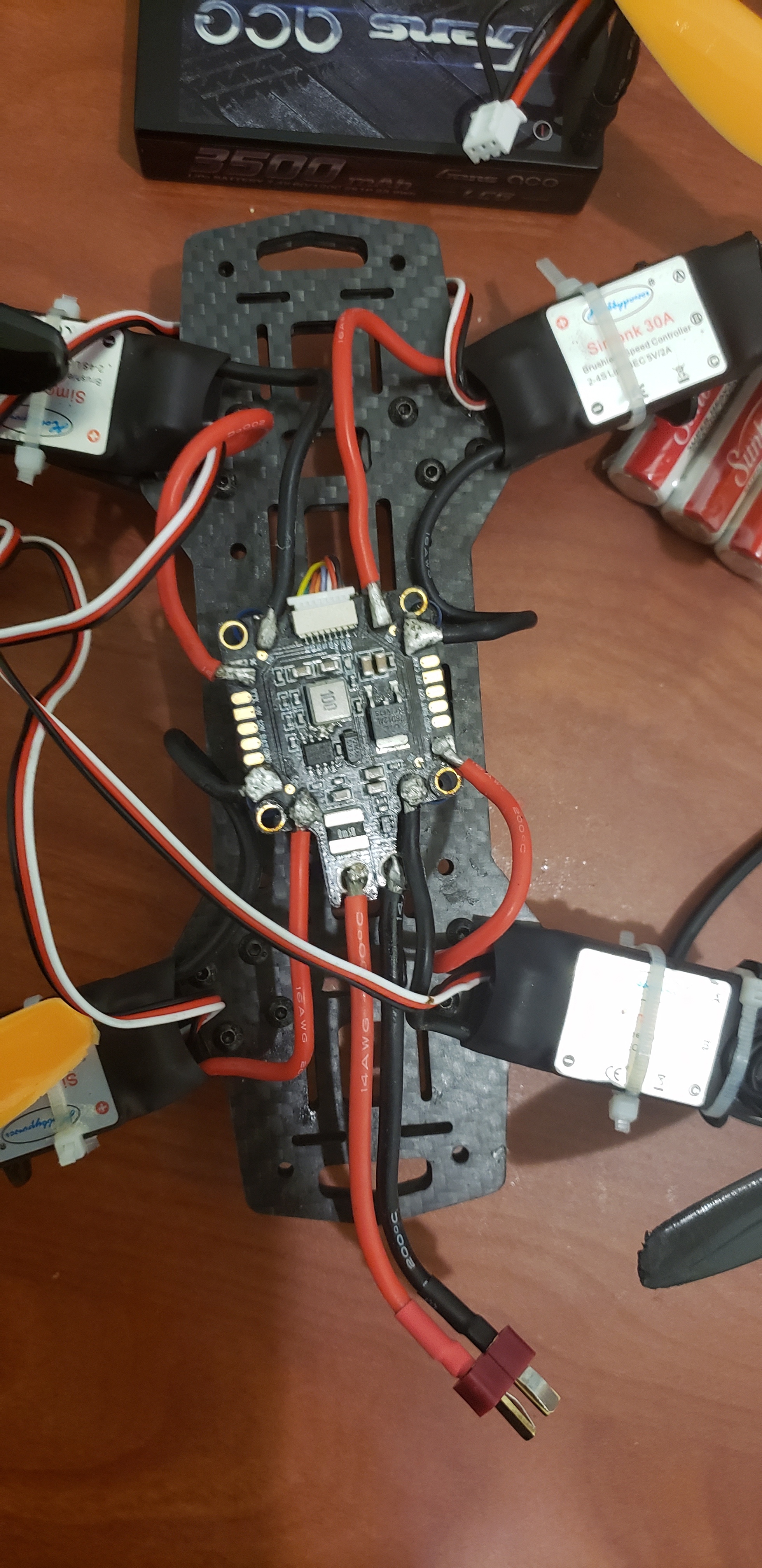
Can you show us how you wired everything up?
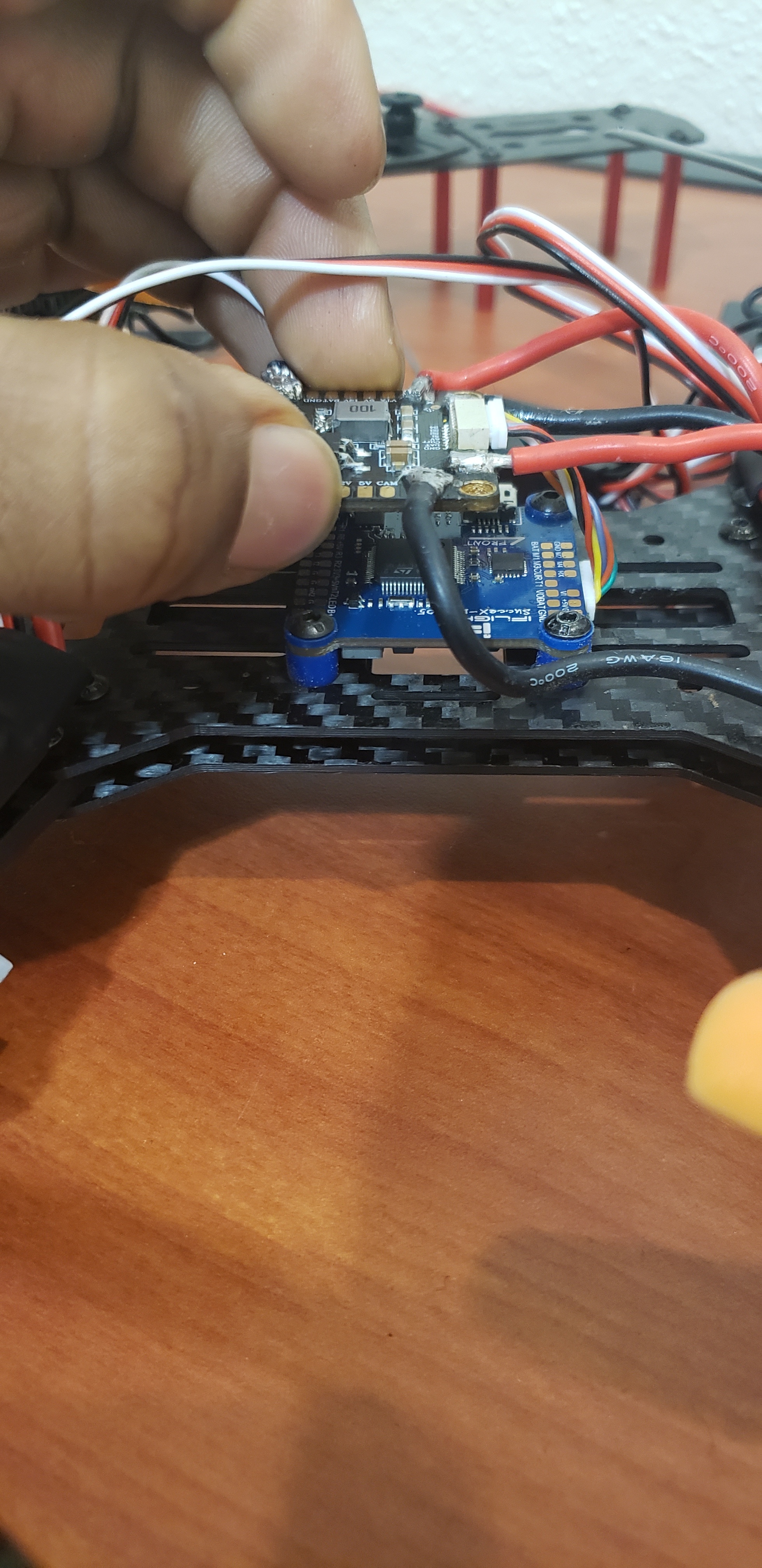
The soldering isn’t the best but I didn’t burn any components. Sorry about being so late to respond.
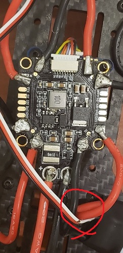
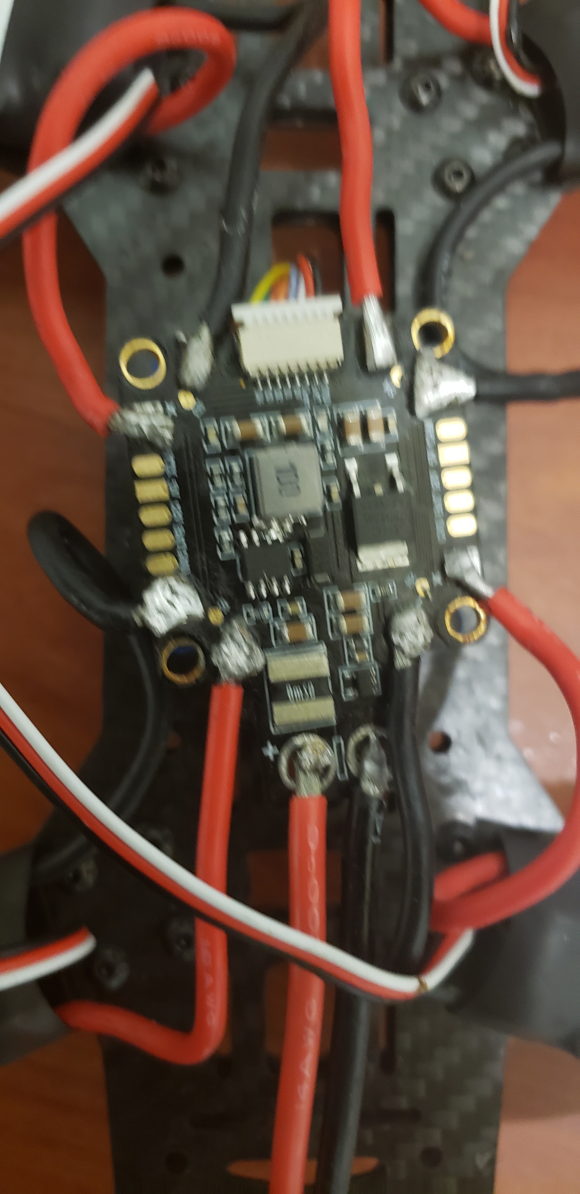
Marked cable does not look that good 
The soldering looks, as you mentioned, not that clean… My tip would be to practise a bit with some spare or old parts if you have them to get a good feel for it.
Also you dont have to strip the isolation that far off. A bit more than half of what you have is enough. Add a good amount of solder to the pad. When the solder is liquid insert the cable (cable should be presoldered). Then hold and let it get solid. If it does not look stable or as you wish, repeat with care or reheat the joint and adjust the wire with some tweezers if you want. Add solder if needed.
Can you show us where the signal cables of your Escs go?
Normally they are soldered to the FC.
OPTION 1:
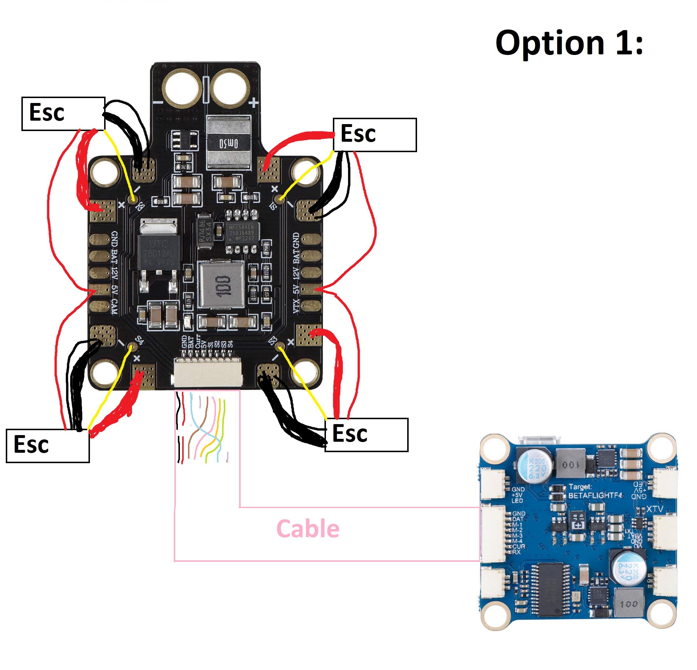
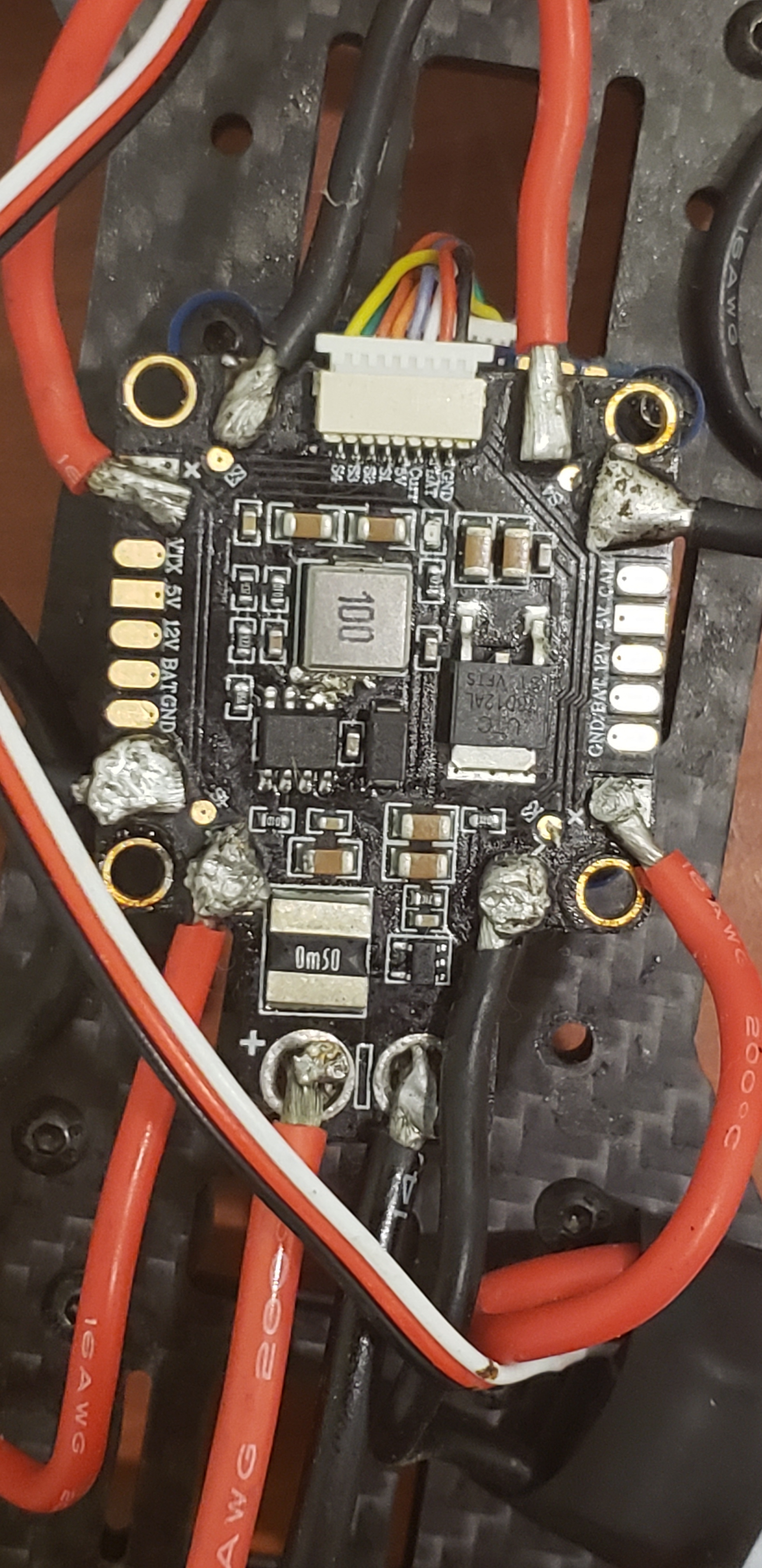
There a really tiny pads between the big ones your escs get their power from. The white cables of the escs need to be connected to them. (I drew them in yellow)
Then connect your FC to the PDB with the cable you have already installed but you have to make some changees to it. Make sure the pins of the Motors match (M4 to S4, M3 to S3 and so on…) Also Gnd and Battery also need to match. I would remove the other pins but you can keep them if you want. Just make sure the pins match.
To change the pinout of the plug you need to carefully bend the little plastic thing holding the metal end of the pin and pull it out carefully. This should go out very easy.
OPTION 2:
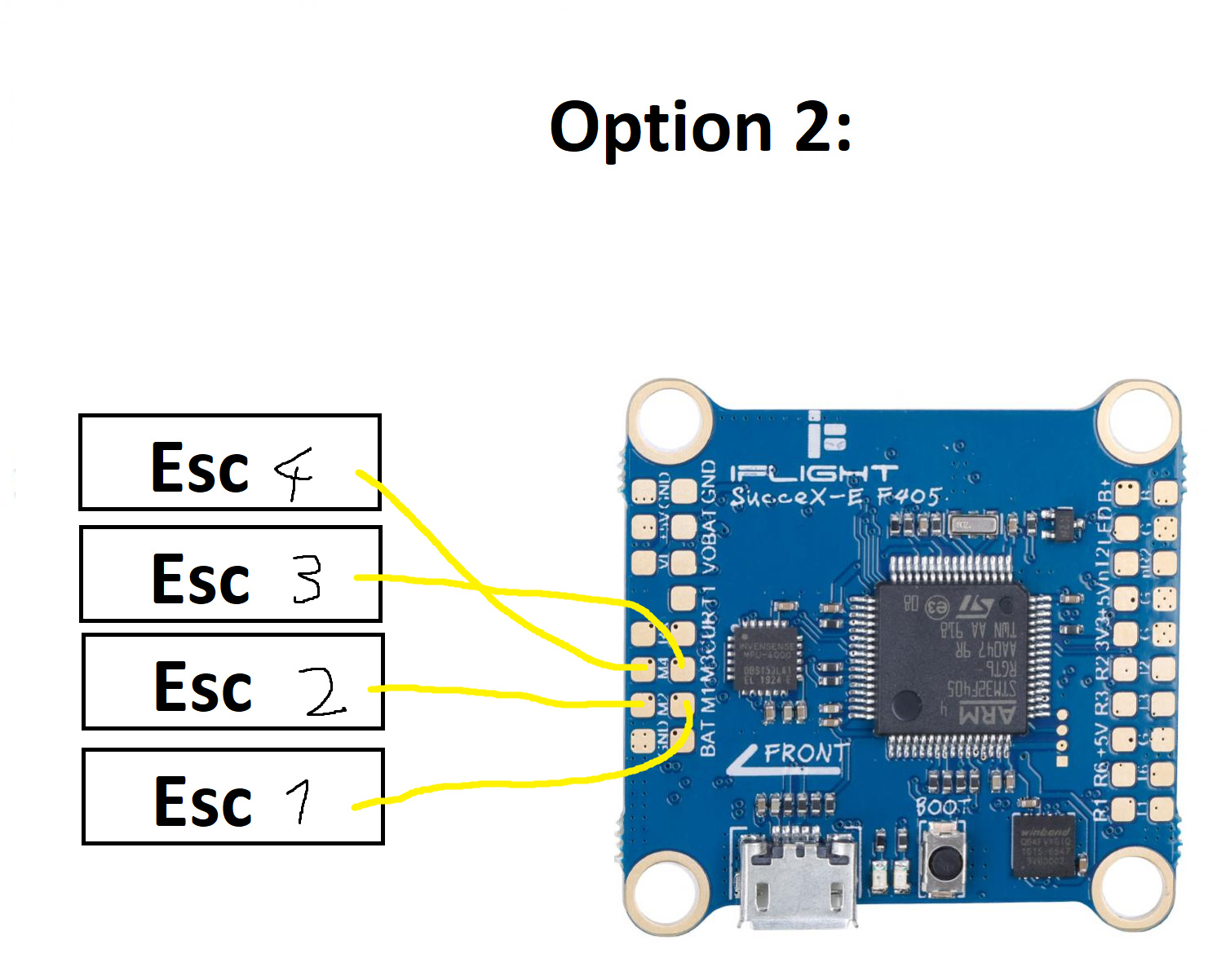
Kinda selfexplaining i guess…
Personally i would prefer Option 1 because it is cleaner but it requires some decent soldering and you will have change the cable.
The soldering on Option 2 is harder because of limited space but it is probably easier to understand.
I can, if you want send you the Original Images via Direct Messages so you can have a close look if you want.
Its better to use SBUS or PPM than to use one channel per esc.
Thats normally done when building planes not drones.
For it to work like you seem to intend to, you will have to hook everything up like shown in my artpieces  .
.
Ok. I’ll give that a try. Thank you!
Wait! How will the transmitter work if there’s no reciever connected?
The Receiver will be connected to the FC as well.
You can use the cable that came with the Receiver or you can recycle an old Esc cable that you cut off when soldering it to the FC.
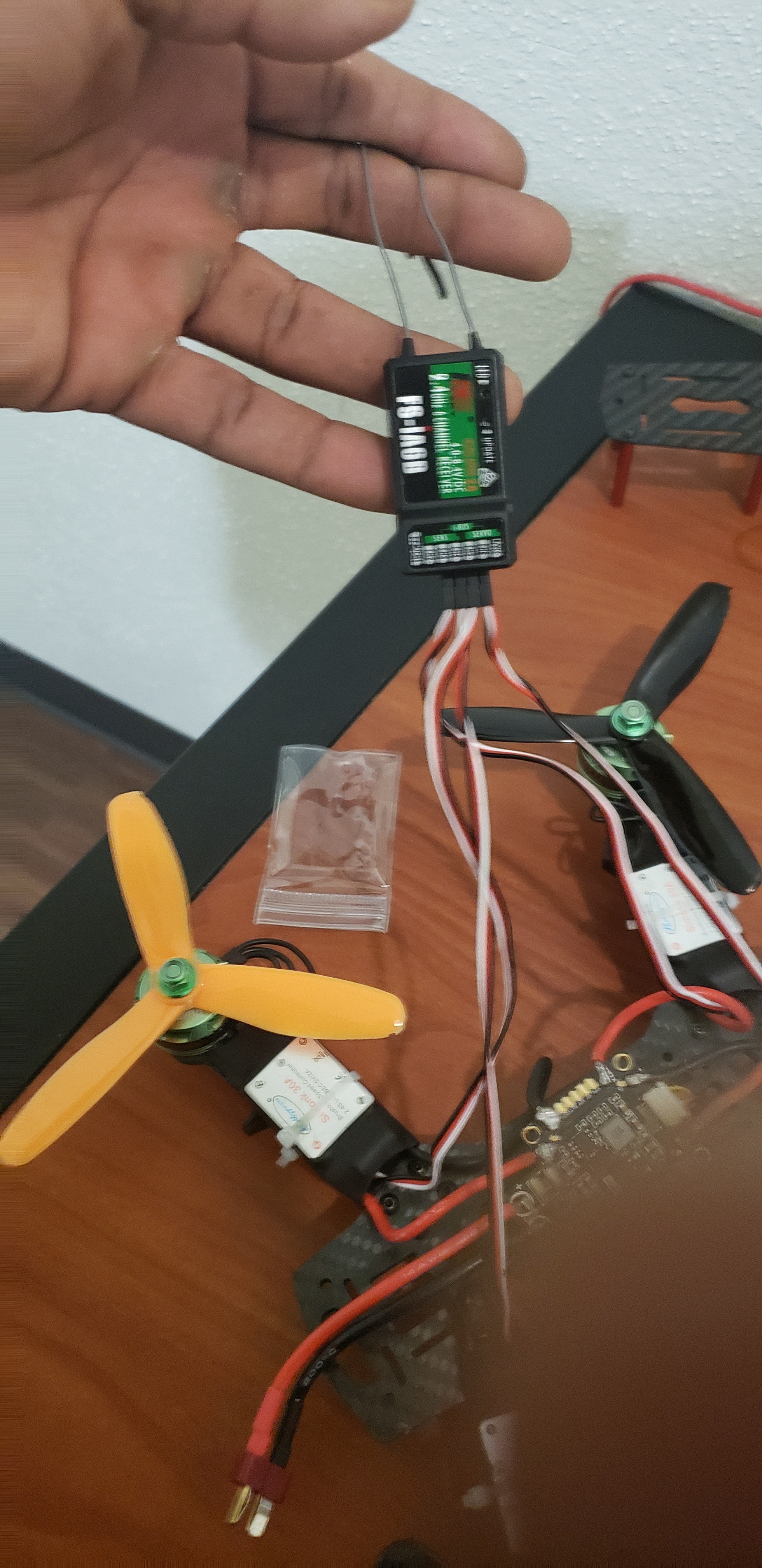
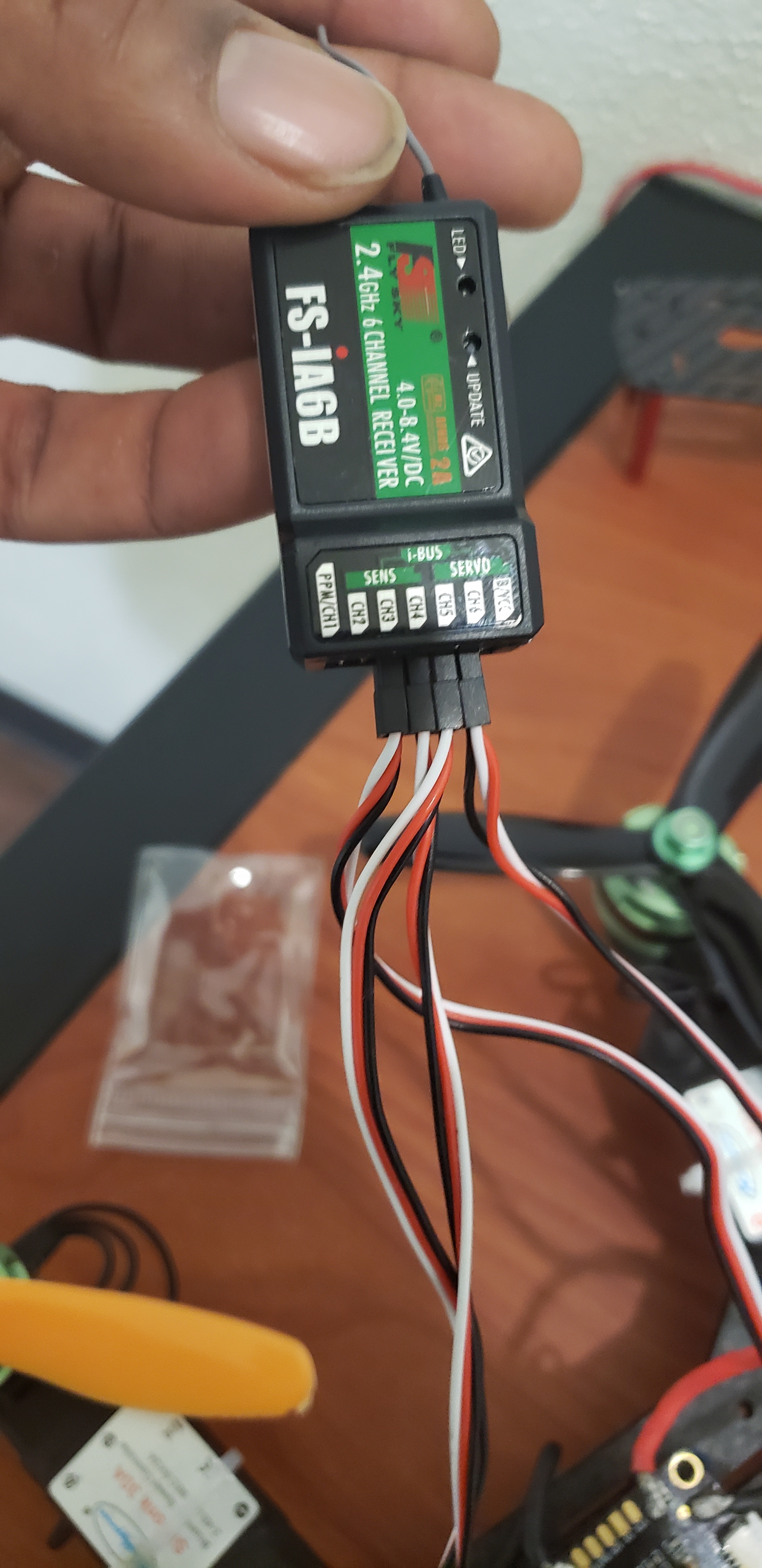
I suggest you use PPM. It is fast enough and especially with Flysky the easiest to setup however im not sure if your FC does support PPM as i cannot find a PPM pin… So we are going to use Ibus ![]()
For that plug the cable into the IBUS Slot of the Receiver (check if orientation is correct, everything should be labeled on the receiver).
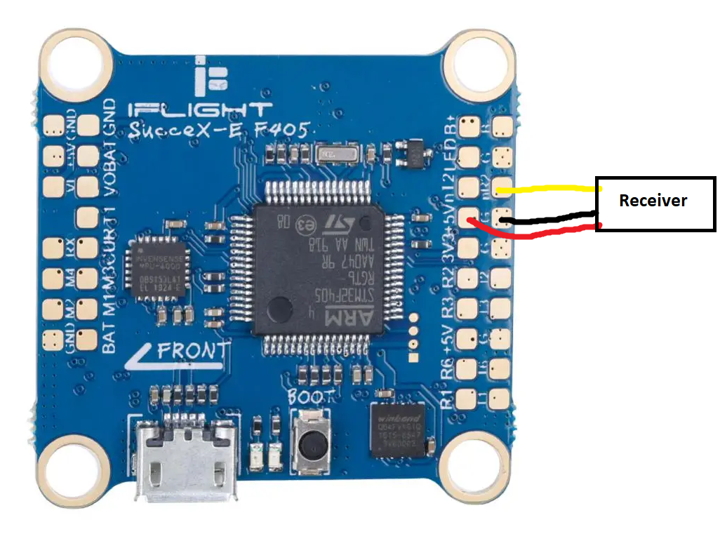
Connect to FC as shown:
Here is a guide on How to setup IBUS in betaflight. (You are using UART 2 so enable Serial RX on that port)
@James_E_Jr Did everything work?