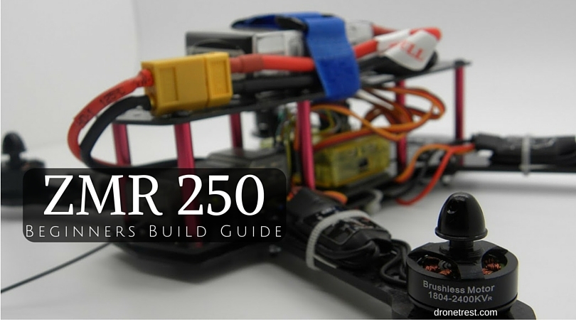
This is another addition to our beginners guide series and this covers the build the ZMR250 mini FPV quadcopter. This kit is a very useful and affordable kit as it includes all the basic components you need to complete your first build. To get this quad in the air, you will need to add a suitable battery, a radio control and a radio receiver that is compatible with that controller. For this kit, we recommend the Tattu 1300mah 45C LiPo battery pack and the RadioLink T4EU 4 channel radio control with R7EH receiver.
If you have any questions at any time throughout this guide, please ask below in the comments section and I’ll be happy to help.
Kit used in this build
- ZMR 250 DIY Quadcopter Kit
- Tattu 1300mah 3S 45C LiPo battery pack
- RadioLink T4EU 4 channel radio control with R7EH receiver
- DroneBuildr Tool kit
- Soldering Iron
- Some bits and bobs (e.g. electrical tape)
Accompanying Video
If you would prefer to see this ZMR250 beginners guide in video form, but we cover more details in the written guide or if you nerd help ask us a question below ![]()

Motor and ESC Connection
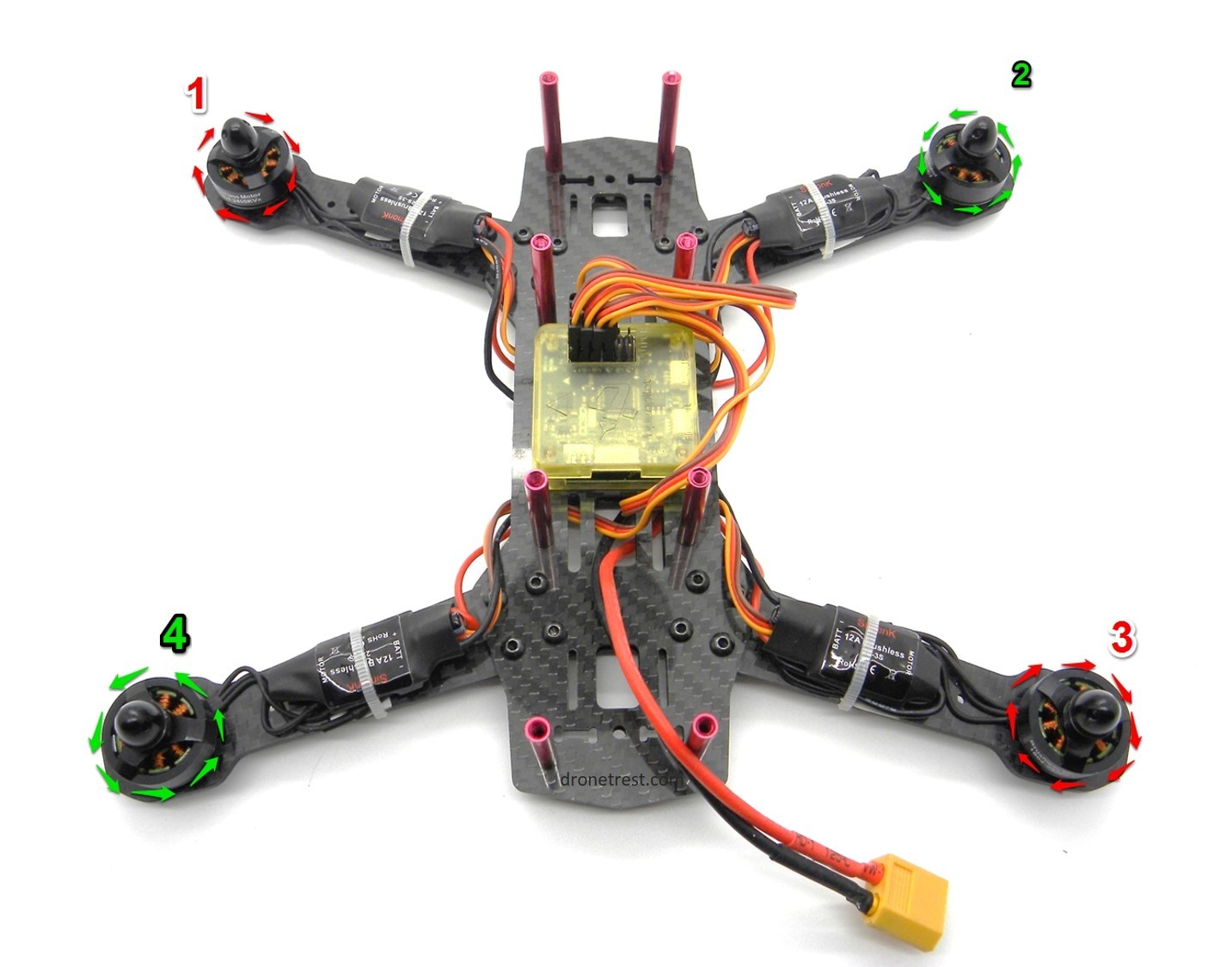
Ok, let’s get down to it. A good place to start is with the motors and electronic speed controllers (ESCs) that you get with this kit. These motors and ESCs now come with bullet connectors and so you can easily connect (and disconnect) them. This may be essential as you must connect the motors cables to the ESC cables in a specific way to ensure they spin in the correct direction. The correct method of connection is shown below.
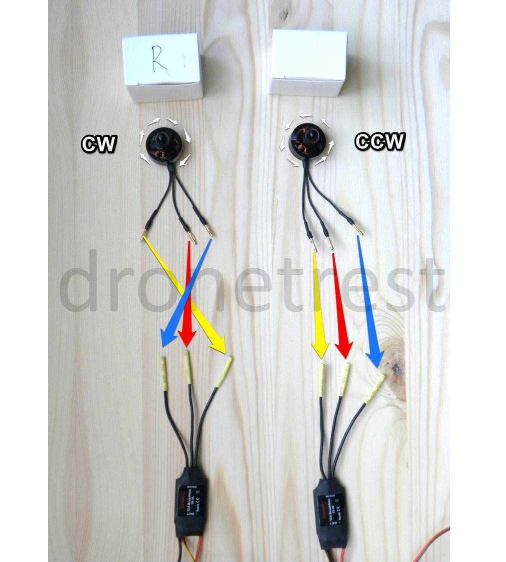
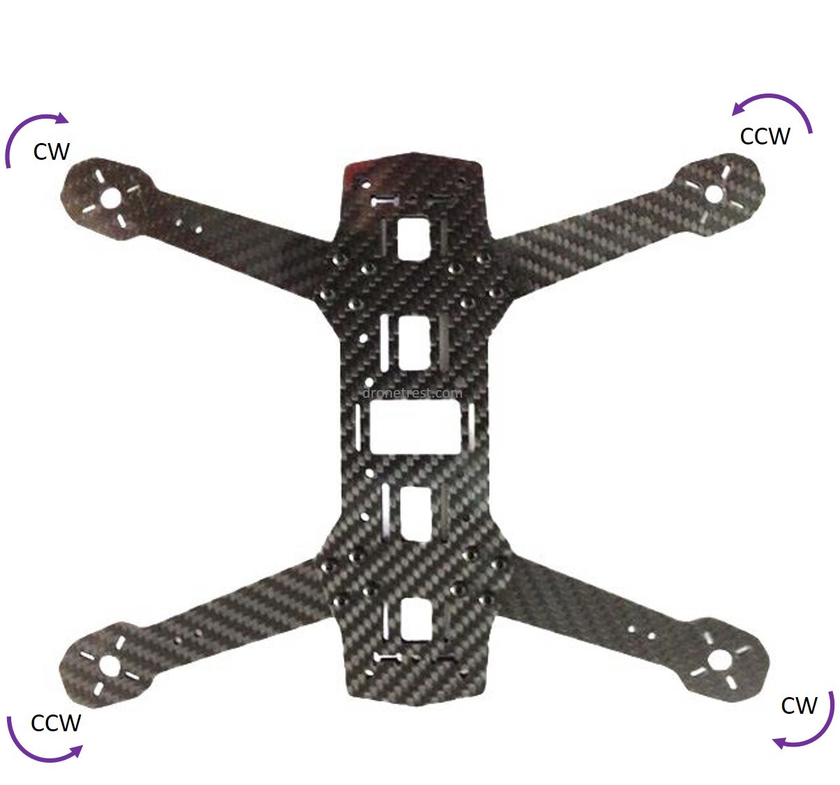
Tip: If you have lost track of the motor orientation, the way the propeller nut unlocks is the direction the motor should spin in. I.e. the motors in the boxes labeled ‘R’ should spin clockwise and their propeller nuts unlock by unscrewing them clockwise.
It’s a good idea to test the motor spin direction after connection. You can do this with the aid of a servo tester and a suitable battery (such as the one recommended for this kit). If you do not have a servo tester, you can just use the radio receiver and radio control.
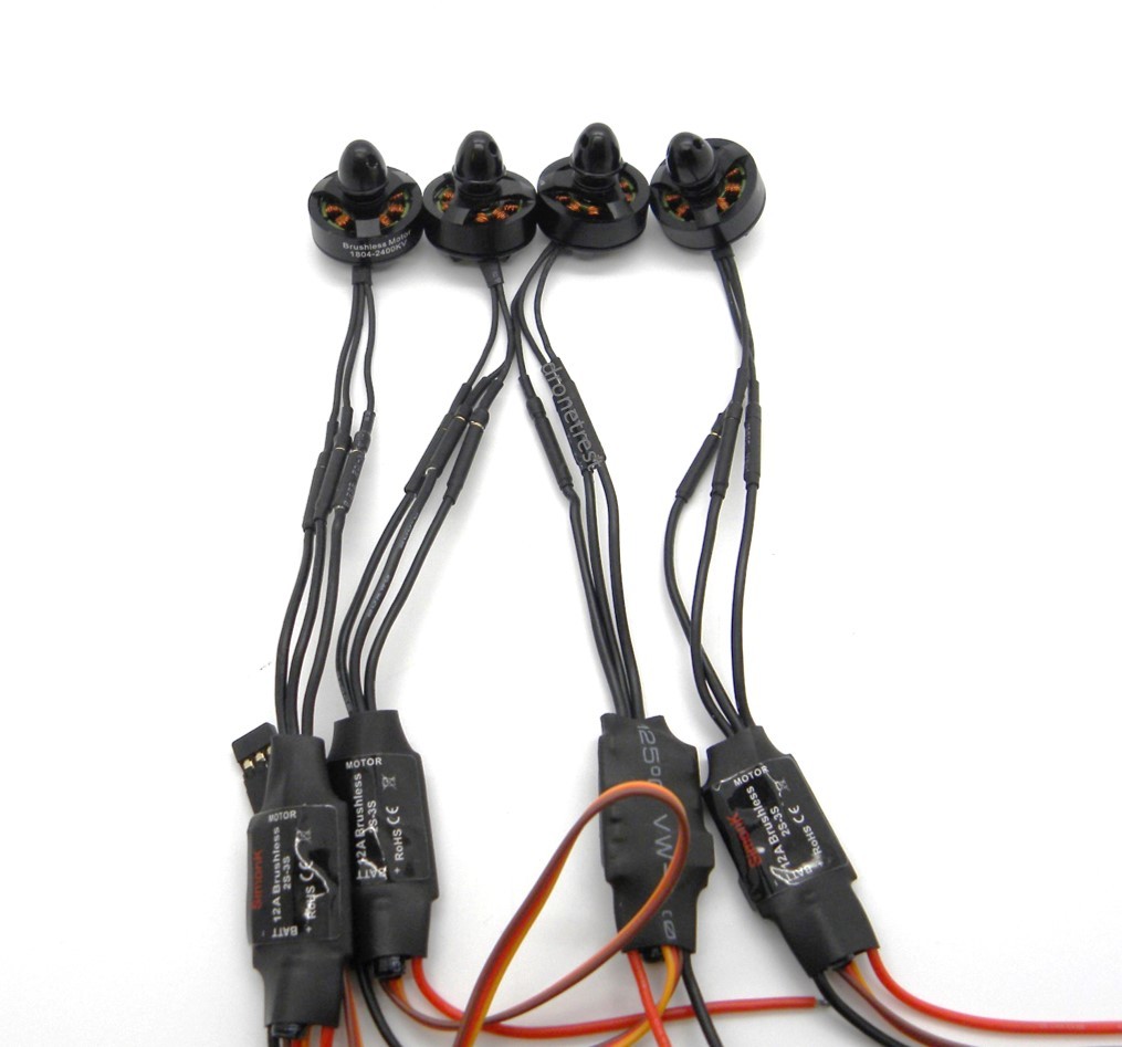
And so there we have it; the motors connected to the ESCs (correctly hopefully).
Motor Installation
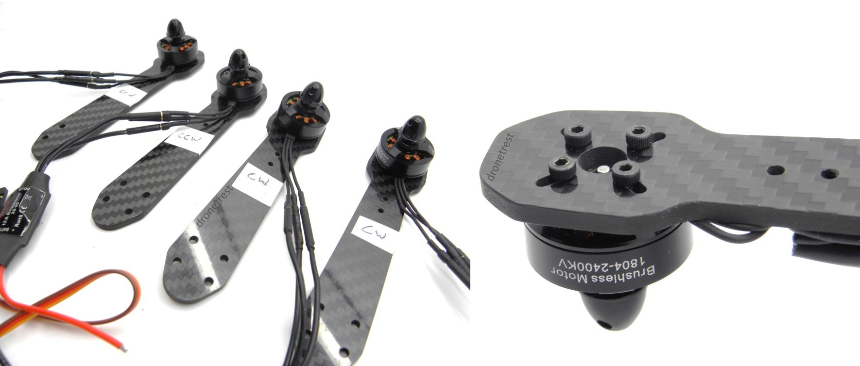
Now we attach the motors to the arms of the ZMR250 mini quadcopter. I have found that it is a good idea to label the arms in relation to which motor you attach to it for future reference. So there are two clockwise (CW) motors and two counter-clockwise (CCW) motors and so we label two arms with CW, and two with CCW (make sure to attach the correct motor to the correct arm). You can label the arms in any way that you wish, here we have used some sticky paper that we had laying around.
Frame Build
Now that we have all four motors attached to their respective arms, we can now get on with most of the frame side of the build. You will notice that there are two bottom plates of the frame (these two are identical to each other) and one top plate, which is more narrow than the other two. The arms (with the motors attached) will be sandwiched between the two bottom plates. Before we do this however, we need to attach the red standoffs to one of the bottom plates as shown below. The arms are then placed under this plate and the appropriate screws are threaded though the holes. Make sure to attach the arms in the correct place corresponding to the image below (this is why we labeled the arms earlier).
Even though the holes themselves are not threaded, it is a good idea to actively screw these in with a hex-cap screwdriver as the holes are quite tight. This turns out to be quite useful as it then holds the arms in place for the next stage.
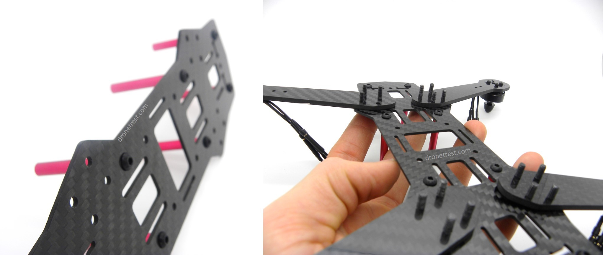
After you have threaded the screws though the one plate and the arms, you must thread the servo cables of the ESCs (the orange, red and brown cable) through one of the conveniently placed holes in the plate (see photos). Make sure to thread these cables through the holes nearest the centre of the plate, on the same side as the ESCs themselves are on.
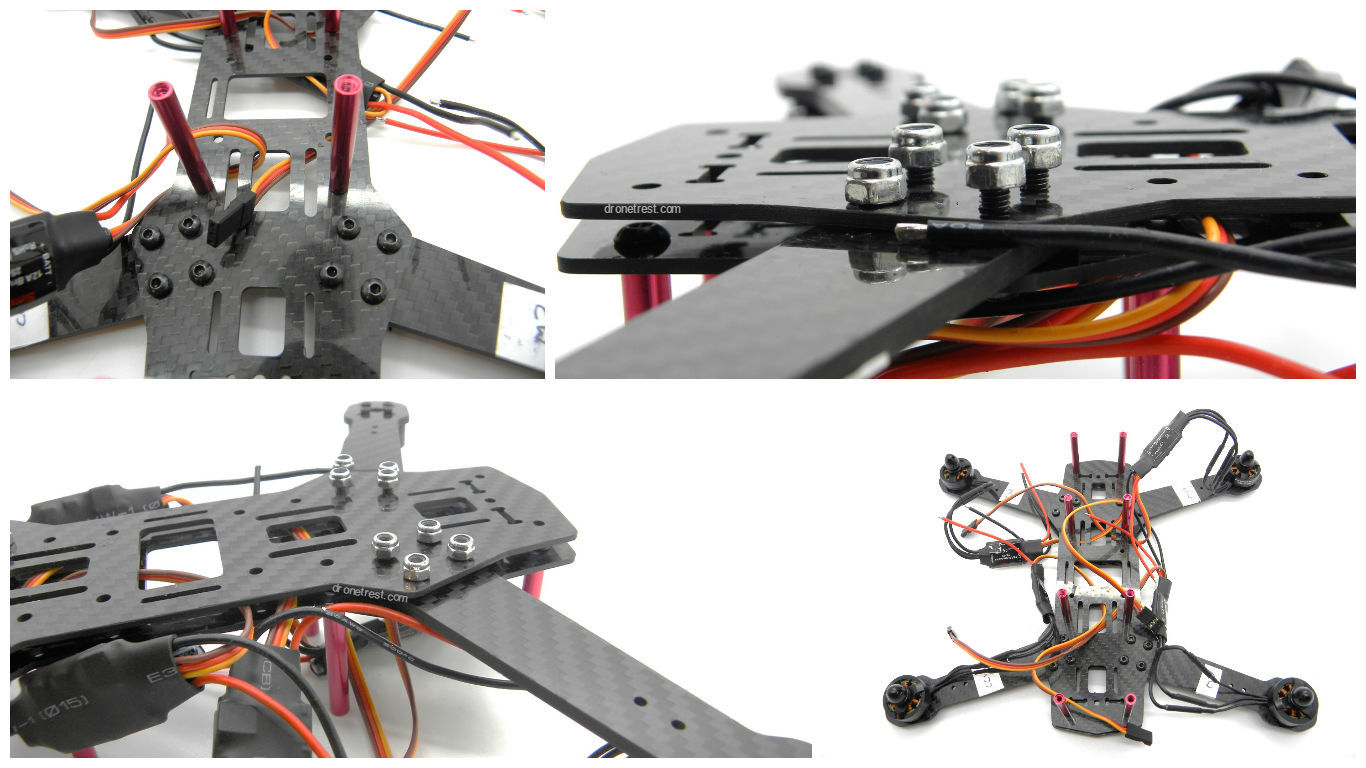
We can now attach the lower plate. You do this by slotting the screws into the plate (or screwing). When doing this, be careful not to wedge any wires between the two plate (i.e. the red and black power cables coming from the ESCs). Obviously, as you have slotted the servo cables through the two holes in the upper plate, these will be sandwiched between the two plates but try to ensure that they are flat rather than vertical when attaching the lower plate. Once the screws are though the bottom plate, then you secure the plate with the nuts provided. These are applied as shown and it is useful to have a hex-cap screwdriver with a socket driver to make this application easier (this are supplied in the DroneBuildr Tool Kit).
Before we move on to the next stage, it is a good idea to label the servo wires from the ESCs (the ones we threaded through the frame). Now, we need to label them as each one corresponds to one specific motor, and each specific motor is numbered. This numbering is specified by the software that we will be using (Librepilot) and this states that the motors are numbered as shown in the diagram below. We therefore label the servo wire from the ESC connected to the motor on the top left arm as ‘1’ and so on. Again, you can do this in any way you wish, we used a non-permanent marker pen here.
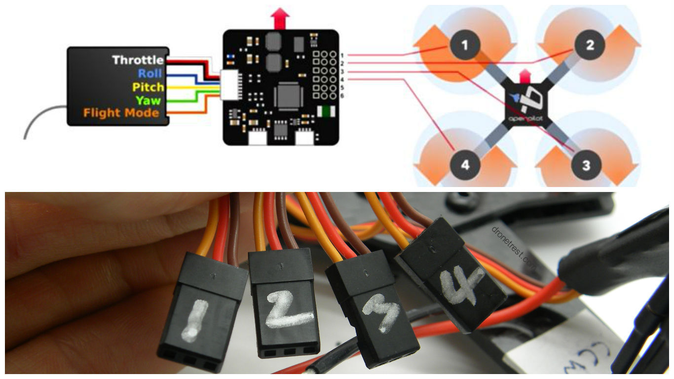
This top diagram also shows you how the ESC servo cables will be connected to the flight controller (that’s the reason for all this numbering) as well as how the receiver is connected - a pretty useful pic that I may be referring back to.
Soldering the battery cable to the power distribution board (PDB)##
So, we now have the majority of the frame built. We have the two bottom plates connected (via the arms) with the red standoffs attached to the top bottom plate… if you know what I mean. We also have the motors attached to the arms, and the motors connected to the ESCs. Perfect. We now start on the soldering of the battery cable to the PDB. In this example, we use the small black PDB provided in the ZMR250 kit as we have found that it is smaller and easier to install. This is going to be attached to the bottom of our quadcopter with the aid of a few of the zip-ties that are provided in the kit.
Those with keen eyes and observational skills will notice that there isn’t a pre-soldered battery cable provided in the kit; there are just some cables and various connectors. We therefore have to first solder the correct connector to the ends of the loose cables. As mentioned previously, we will be using the Tattu 1300mah 45C LiPo battery pack (which comes with an XT60 connector) and so we must solder the provided XT60 connector to the loose cables (please use the 16awg size cables). Please ensure that the correct wires are soldered to the correct ports in the XT60 connector as we don’t want to be connecting red cable with black and vice versa when you plug it into the battery… this would not end well. This process is a bit tricky if you’re new to soldering and so we have created a quick video guide on this to help you out.
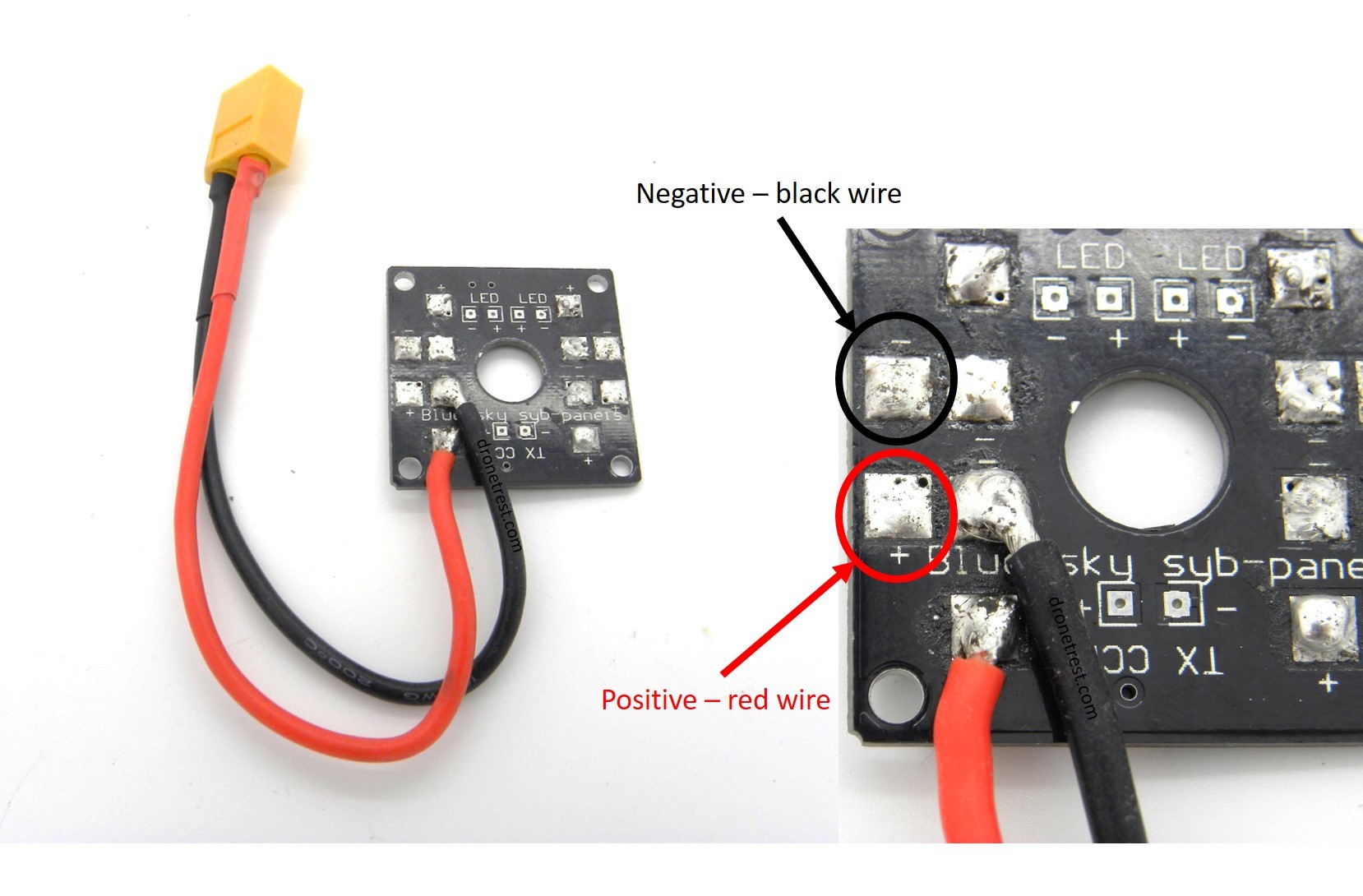
Once we have the battery cable soldered and ready to go, we solder it to the PDB as shown. The most important thing to remember when completing this step is that there are two kinds of pads; negative and positive. The black wires have to soldered to a negative pad and the red wires have to be soldered to a positive pad. It’s also important to solder the battery cable to these exact pads on the PDB as we need room for the ESC cables.
Soldering tips. If you are new to soldering, here are a few quick tips:
- Once the iron is hot, dab a bit of solder on the tip to focus the heat;
- For soldering PDBs, first add a bit of solder to the pads before trying to solder the ESC wires onto them;
- ‘Tin’ the ESCs wires by covering the bared tips with solder;
- When soldering the ESCs wires to the PDB, place the wire on the appropriate pad and then touch the wires with the iron tip. It will take a few seconds to heat the solder and the wire will ‘sink’ into the solder previously applied to the pad. Ensure that most of the wire tip is covered with solder.
Soldering the ESCs and attaching the PDB
We can now use the skills you learnt in the last step (if you didn’t have them already) to solder the ESC power cables to the PDB. These cables are soldered to the pads that make the most sense space-wise. The entire connection diagram for this quad is shown below.
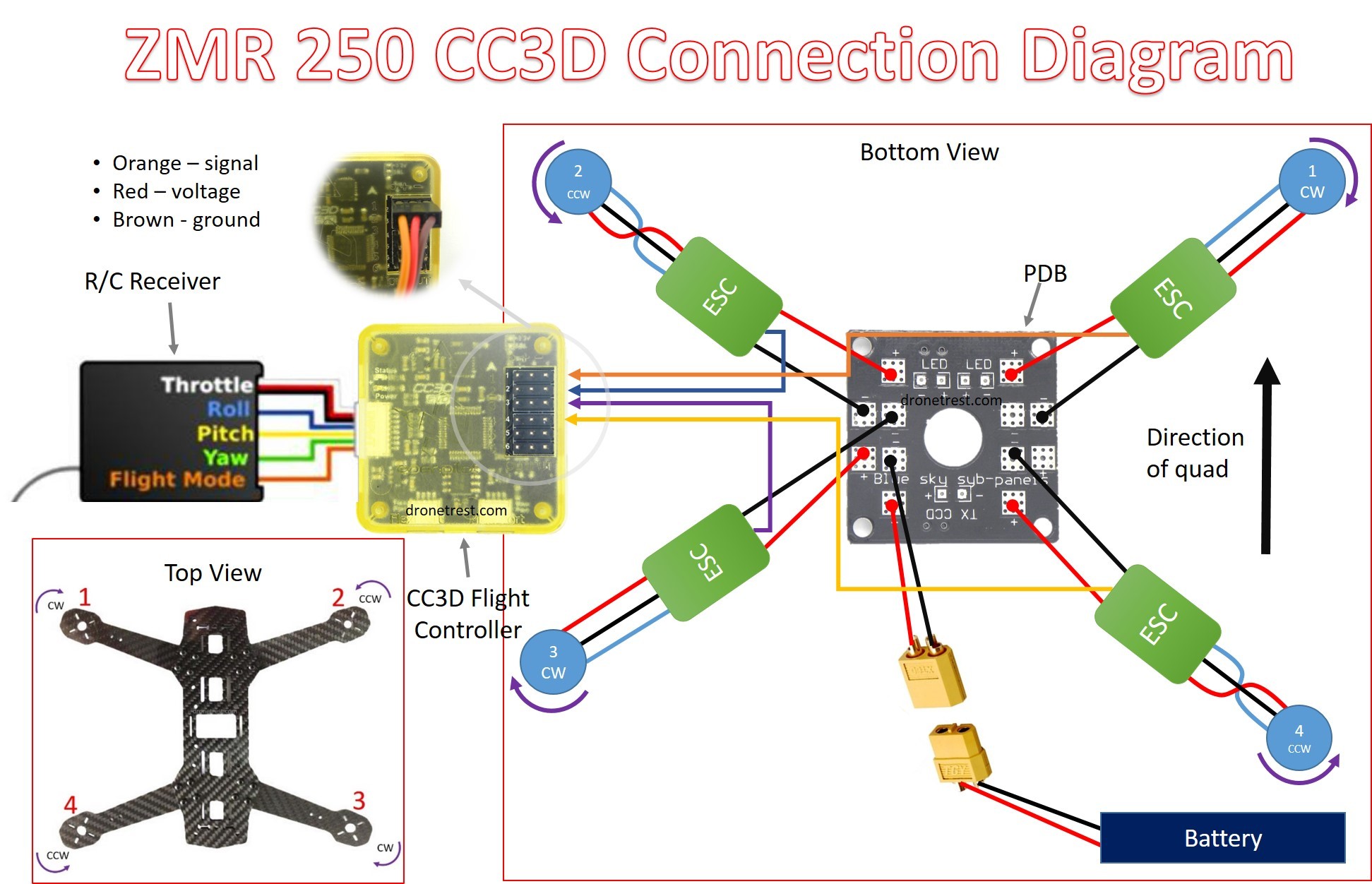
Don’t worry if this seems a bit complicated now; we will go through this step by step. This diagram will hopefully be a useful device to refer back to throughout your build. As we will install the PDB on the bottom of the ZMR250, we have a bottom and top view in this diagram to represent what you need to do clearly (that’s why the motor positions change). Here’s what the PDB should look as you solder on the ESCs.
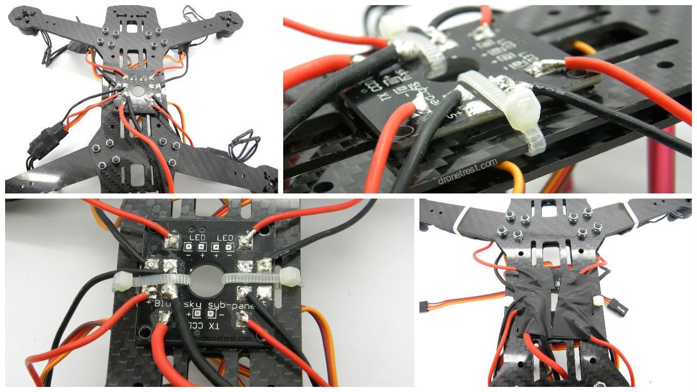
After completing this job (with perhaps a few hiccups along the way), we can secure the PDB onto the frame. We do this with some of the zip-ties provided in the ZMR250 kit. The application of these is fairly straight forward but there are a few things to look out for. Firstly, avoid trapping the power cables inside the zip-ties when applying, we don’t want any severed ESC power cables. Slip the zip-ties around only one of the bottom plates for more security and thread up through the hole in the PDB.
Tip: to make this easier, bend the tip of the zip-tie before attempting to thread it through the two bottom plates. This will make it much easier to then thread it through the PDB hole.
Once we have done this, we must then cover the PDB with electrical tape. Unfortunately, this is not provided in the ZMR250 kit but it can be purchased easily from online shops such as eBay. We do this to ensure that the board doesn’t short-circuit.
Securing the ESCs and Installing the CC3D Flight Controller
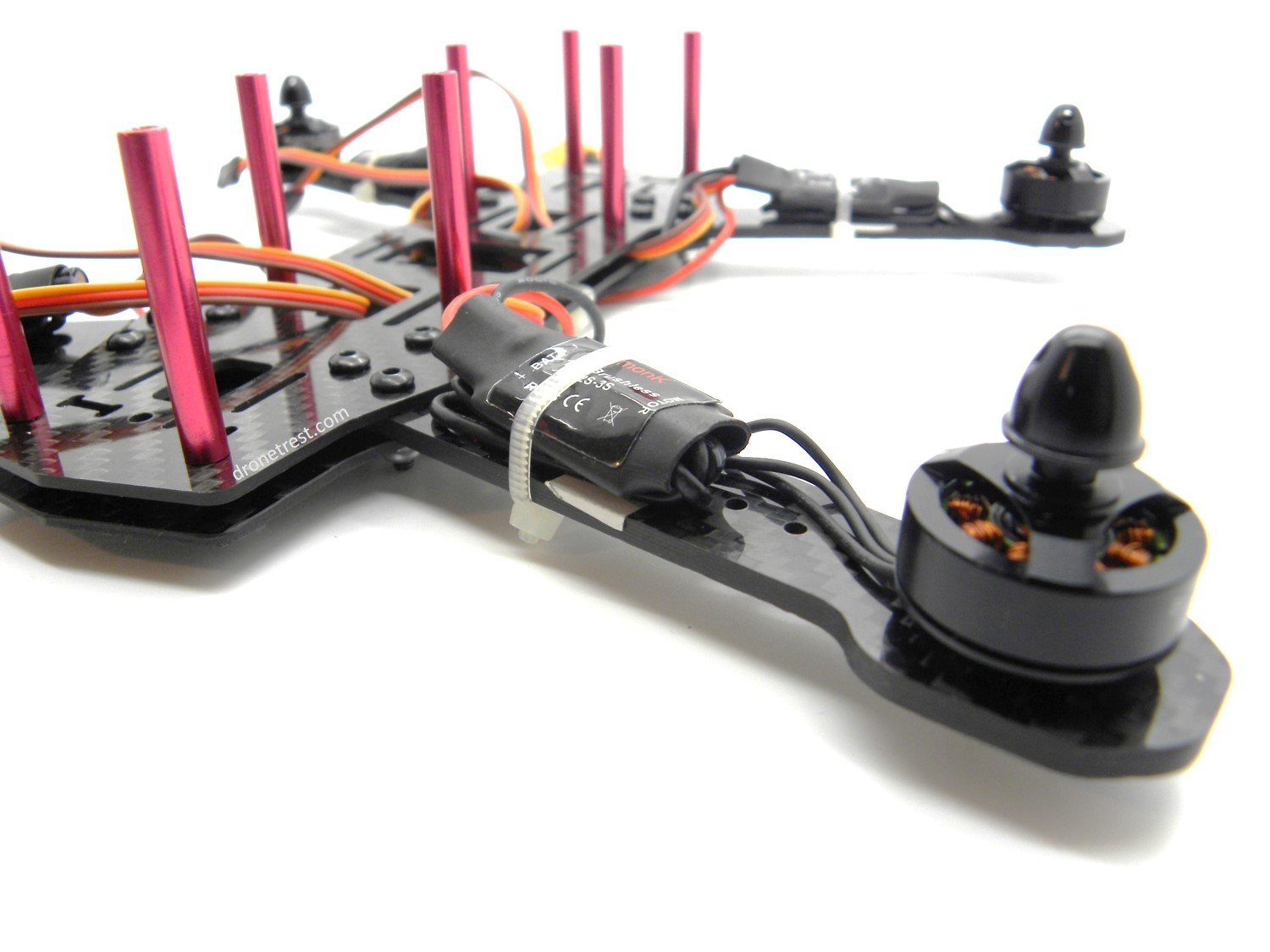
We now have all the ESC power cables soldered to the PDB and the PDB itself is fastened to the frame. We no need to quickly secure the ESCs themselves onto the arms of the frame. We again do this with some of the zip-ties provided in the ZMR250 kit and we simply put one zip-tie around the middle of the ESC and the arm. Be sure to fold any excess cables underneath the ESC before tightening the zip-tie and ensure that no cables impede the motor in any way.
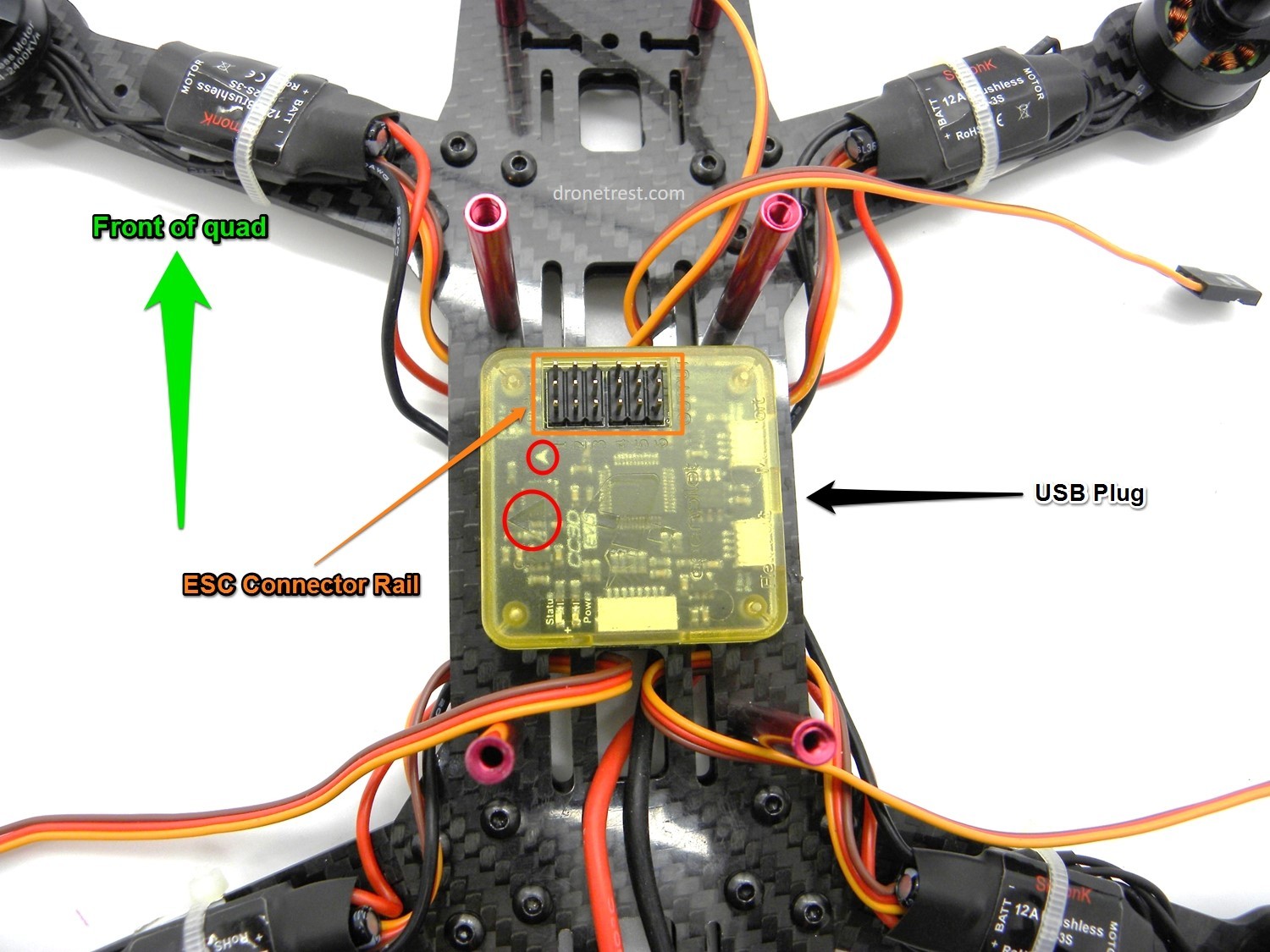
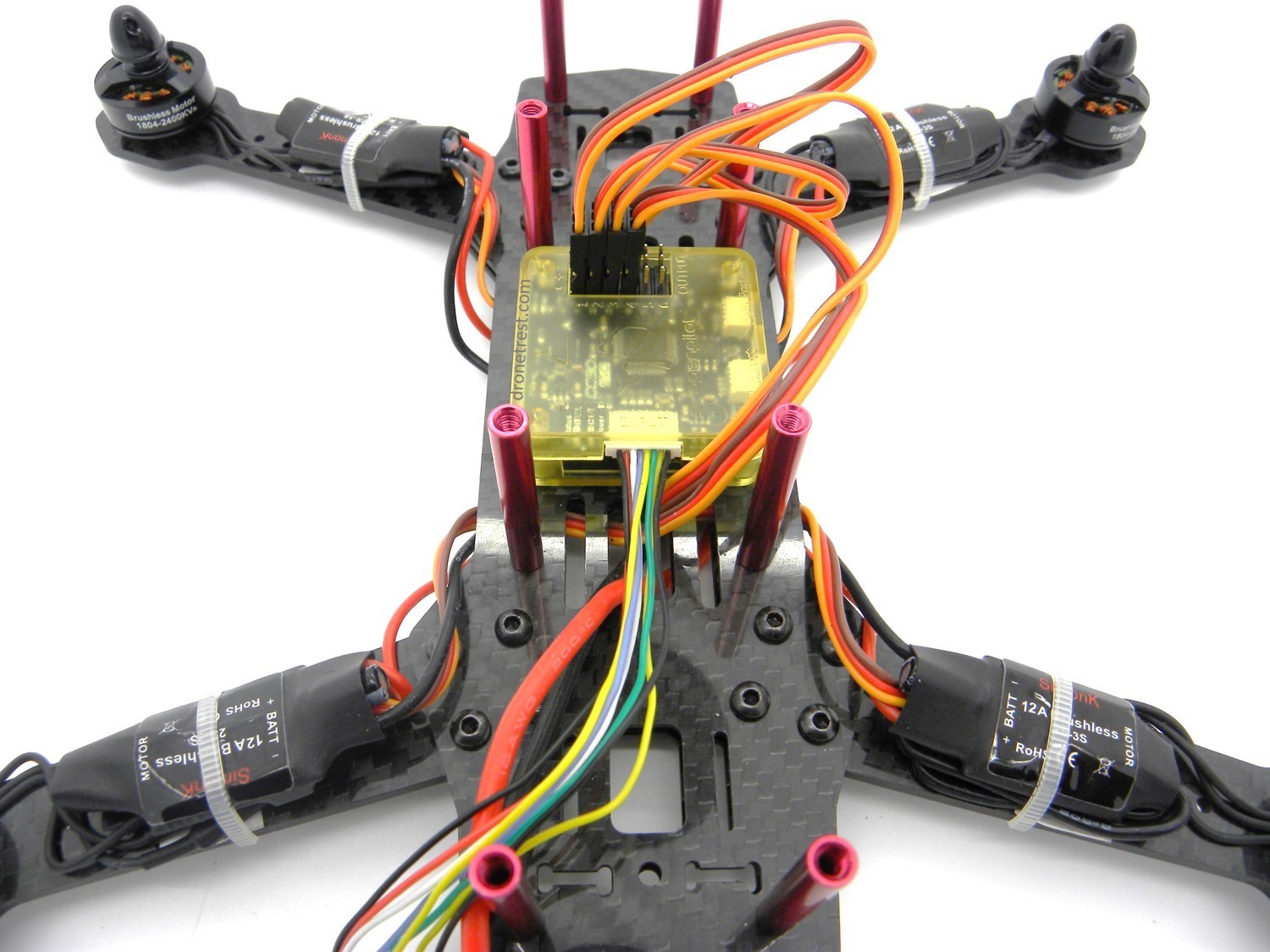
Once this is done, we move on to installing the CC3D flight controller. The best way to do this is by using the 3M double-sided mounting foam which is included in with the CC3D. Be careful in regards to the orientation of the board when you apply it to the frame as the best way of mounting it is contrary to the arrow that is on the CC3D flight controller (highlighted in red in the picture below). We mount it this way as we need to be able to access the USB plug when we have completed the build (for configuration). Placing the USB plug to the side of the quad is therefore the best. The ESC connector rail shown in the photo shows where we will be plugging in the ESC servo wires in the next step.
Connecting the ESCs to the CC3D
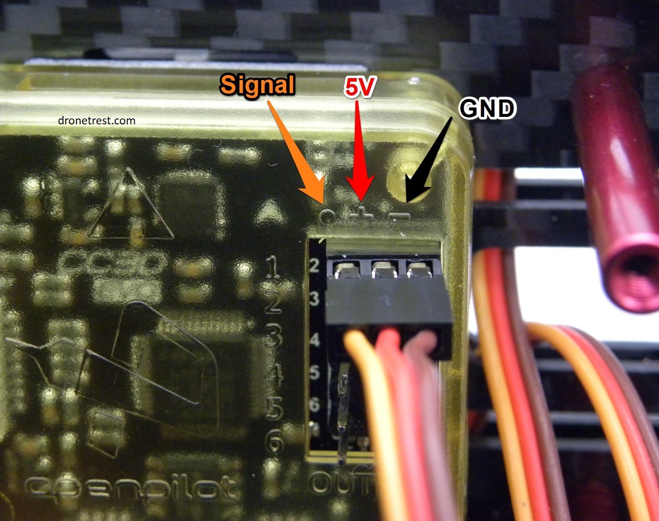
Now we come to plugging the servo wires (brown, red and orange cable) into the CC3D flight controller (so the flight controller can tell the ESCs what to do). This is where the numbering of these cables comes in handy as now we simply plug the ESC wire labeled ‘1’ into the set of pins that is also labeled ‘1’ etc. You must also take care to plug in the servo cables in the correct way. In the picture below, you will see that the pins are labeled with a ‘o’, a ‘+’ and a ‘-’. The ‘o’ corresponds to the orange wire (signal), the ‘+’ corresponds to the red wire (5V) and the ‘-’ corresponds to the brown wire (ground). You must ensure that all the servo cables are plugged in this way.
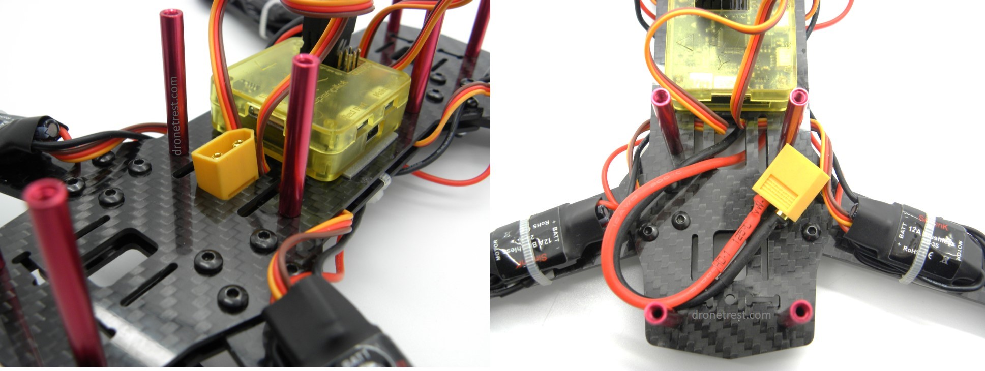
At this point, it is also a good idea to thread the battery cable (the first thing we soldered to the PDB) through the frame, through the hole nearest the CC3D board as shown. The cable will just fit through this hole (conveniently) and it is a good idea to do this so the installation of the battery later on is easy.
Check Point
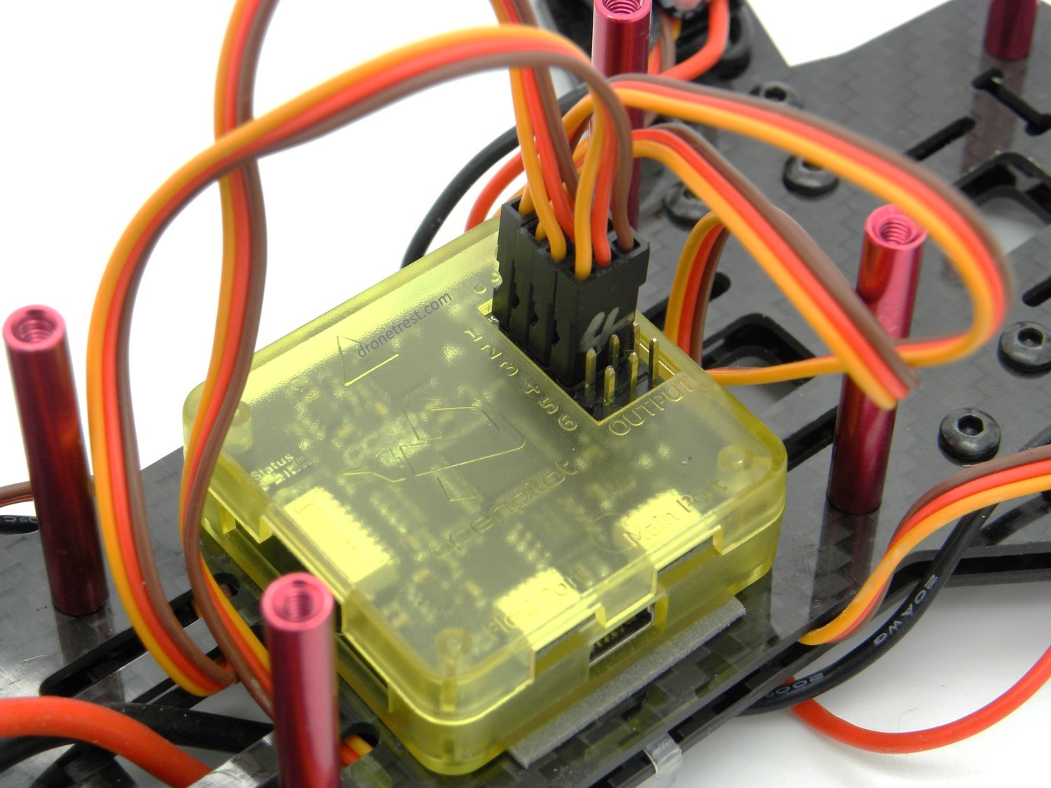
So, we’re pretty much there at this point as far as the build goes. Below is an image of what we should have at this stage. We have the motors attached to the arms, the ESCs soldered to the PDB and we have the servo cables from the ESCs connected to the CC3D flight controller.
We now go on to the installation of the radio receiver and the final stages of the build.
Connecting the Receiver
Connecting the receiver is a simple task with the CC3D as the necessary cable comes with the flight controller and there are no unnecessary complications. So, to begin with, we simple insert the cable into the input port of the CC3D. This is the one directly facing the back of the quad and the cable goes in as shown below.
We then move on to connecting the other ends into the receiver. The receiver we are using here is the R7EH receiver that comes with the Radiolink radio control. We plug each wire into the receiver as shown. The order of the wires follows that of the end plugged into the CC3D board i.e. white, blue, yellow, green, yellow, black. You do have to be careful which way around you insert these wires. You will notice that of the eight separate wires in this cable pack, three are grouped together into one connector, and the rest have their own separate connector. The group of three consist of a signal wire (white), the 5V wire (red) and the ground wire (black). This is the only cable that actual powers the receiver and the others are simply signal wires. All signal wires have to be plugged into the top row of pins (as this is the signal row). The correct way of doing this is shown below.
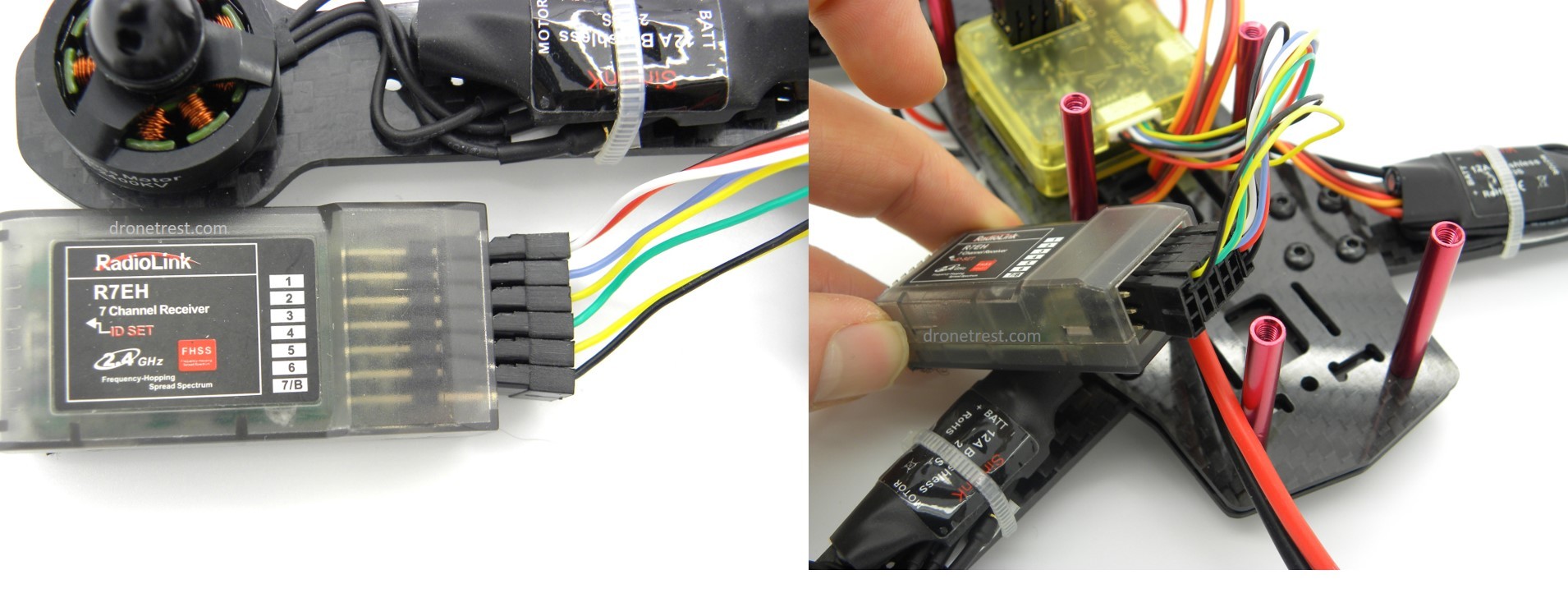
Note: each one of these wires corresponds to a function on the radio e.g. throttle, roll, pitch etc.
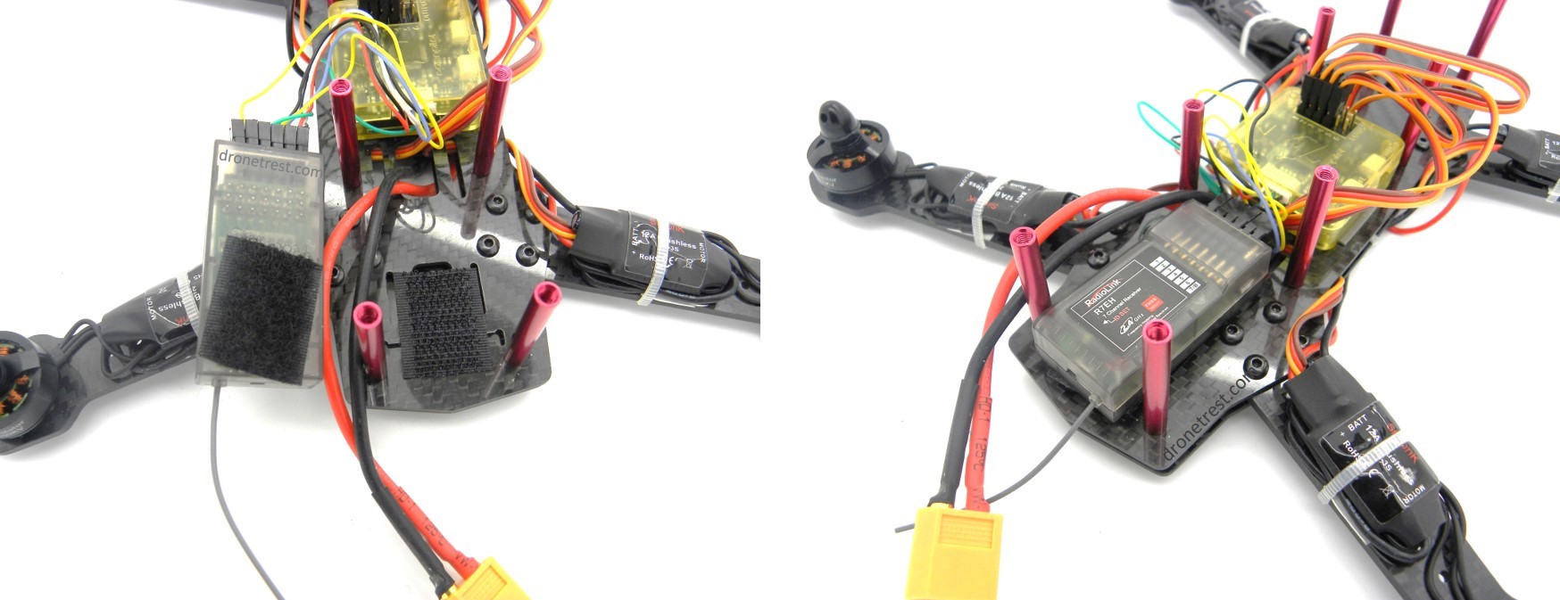
We now fasten the receiver to the frame. An ideal place is just behind the CC3D board and we find that it is best to use some adhesive-backed velcro here (so you can easily unfasten the receiver if you need to). You simply apply one side to the receiver, and one side to the frame and stick it down.
Final Build and Adding the Battery
So now we just need to add the top plate of the frame and then the battery, exciting! We attach the top plate with the small screws left over and the battery will sit on top of this plate. We secure it with the velcro strap that is included with the ZMR250 kit. It’s a good idea to bend the battery cable back on itself and secure down with the velcro strap so that the cable is not protruding out of the main frame.
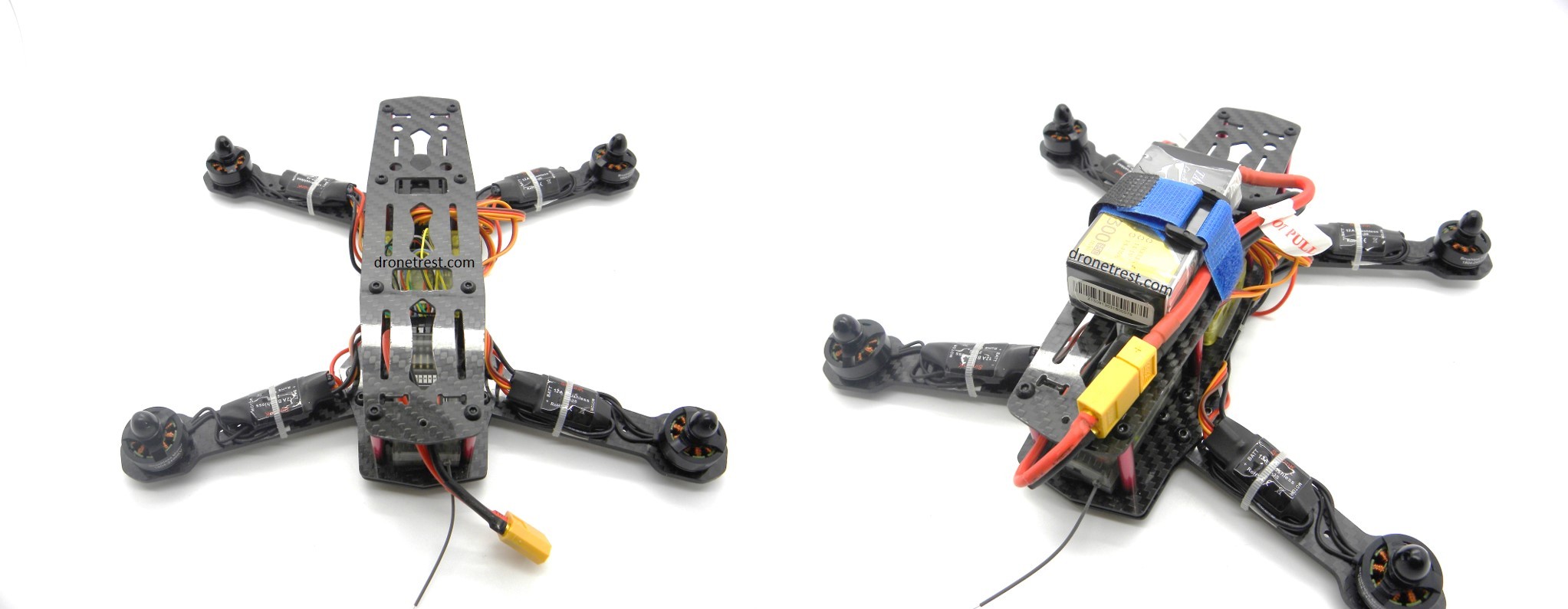
And there we have it, build done (minus the propellers)! We’ll leave the props off for now as we now need to configure the CC3D flight controller and to decrease the chance of finger loss, it’s always a good idea to leave the props off.
CC3D Flight Controller Configuration
Now all you have to do is configure the CC3D flight controller. We figured this part was easier shown via the medium of video so please check out our ZMR250 CC3D Configuration Guide with LibrePilot video below…

Propeller Installation
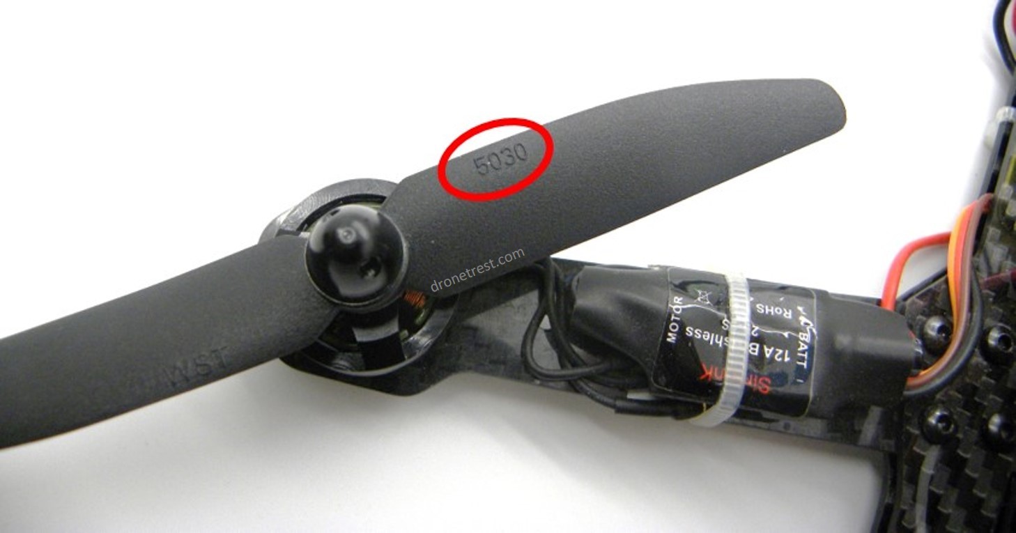
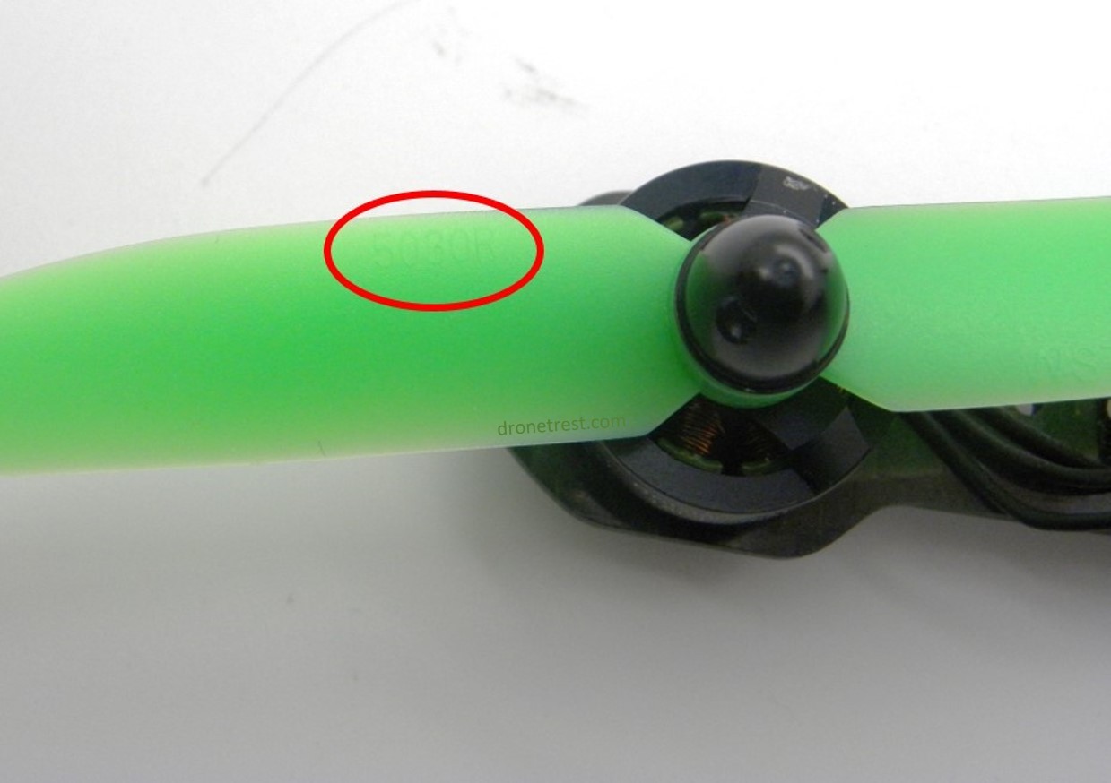
So after the CC3D configuration, we’re basically done! All we need to do is attach the propellers which is a pretty simple process. You just need to be aware that there are two different types of propellers; counter-clockwise (CCW) and clockwise (CW) spinning ones. You therefore need to attach the correct props to the correct motors.
So, the propellers provided in the kit have either 5030R or 5030 marked on them. We need to attached a propeller marked with 5030R to the top left and the bottom right motor. Subsequently, we need to attach a propeller marked with 5030 to the top right and bottom left motors as the pictures below show.
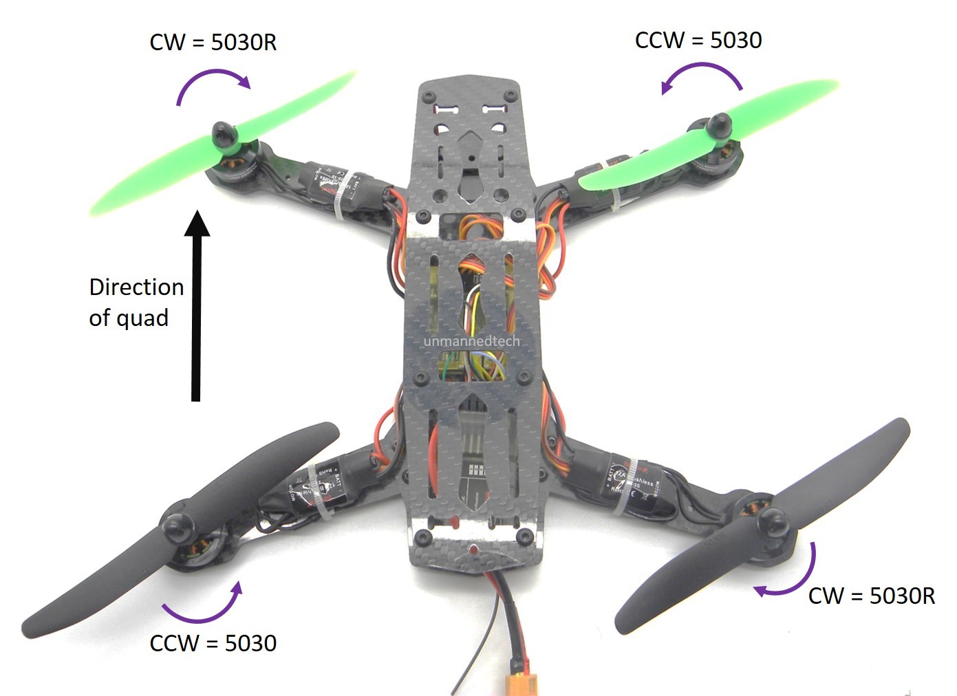
There should be two different colours of propellers in your kit also (in this case green and black). It is useful to attach two propellers of the same colour to the two front motors, and two propellers of a different colour to the back two motors. This is so you can easily see the orientation of your quad when it’s up in the air and you’ve maybe lost track of which way it is facing.
Note: There are plastic prop adapters with these propellers but you do not need to use these as the props fit pretty perfectly without them.
The End!
And there we have it! A fully-assembled, fully-configured ZMR 250 mini quadcopter! You can now plug in the battery and go flying! This kit obviously has no FPV gear attached (yet) but it is probably a good idea for you to go out and get some flying practice before attaching the FPV gear (as this will add more cost in the event of a crash…). Please see our How to add FPV to the ZMR250 Guide to learn how to add FPV gear (unsurprisingly!).
Happy flying and don’t forget, if you do have any questions, please let me know in the comment section below and I will do my best to get back to you quickly.


