We are happy to say that we now sell the NerdCam 3D, a stereoscopic FPV camera. Unlike other FPV cameras the nice thing about this one is that you only need a single video transmitter as the nerdcam 3d takes care of combining and overlaying the video signals from two cameras to give you a 3D effect.
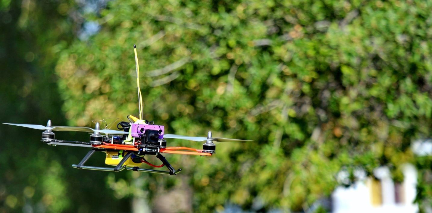
The NerdCam3D is a unique board camera which creates a stereoscopic analog video signal (CVBS). Unlike other 3D-board cameras the NerdCam3D supports both Field-Sequential 3D and Side-by-Side 3Dvideo in NTSC as well as in PAL. This feature makes the camera compatible with a wide variety of legacy and state-of-the art video goggles. The video signal created by the NerdCam3D can be fed either directly into the video goggle‘s AV-port or through single-channel wireless video transmission gear. Therefore, this 3D-camera is perfectly suited for all First Person View (FPV) applications. In particular, those users already operating an 3D-capable FPV video goggle now can enjoy stereoscopic perception just by swapping their present FPV-camera for the NerdCam3D. In addition, the camera features a built-in stereoscopic on-screen display with basic status information like battery voltage, current consumption and flight time.
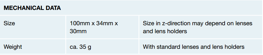
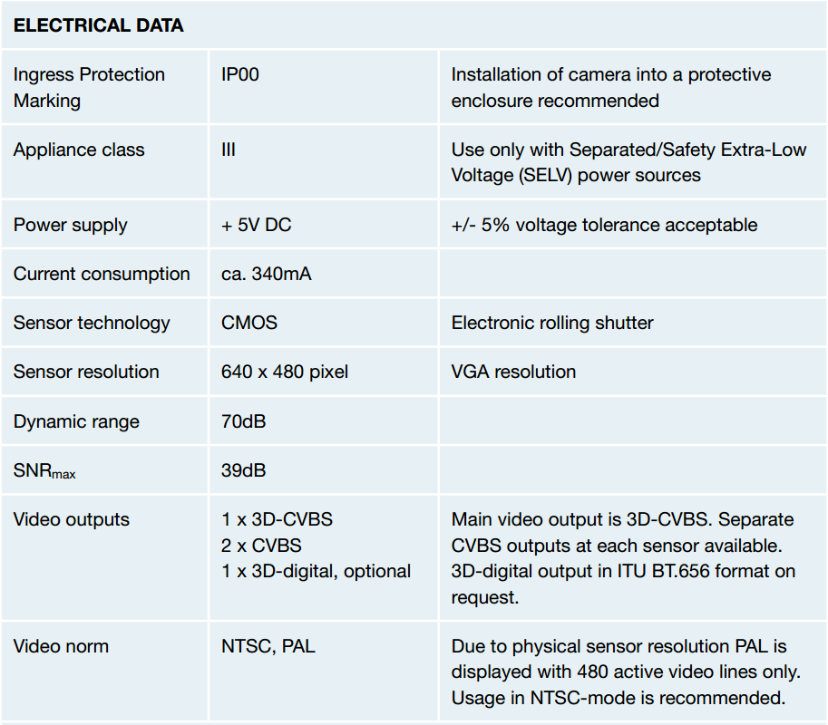
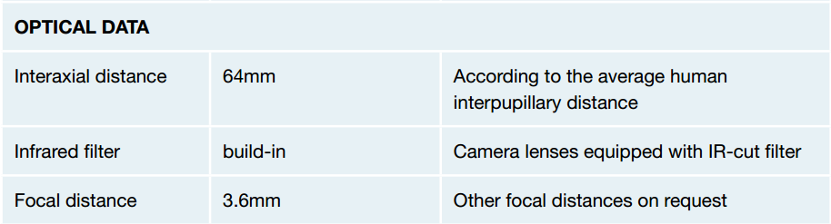
Specifications
Supported Goggles
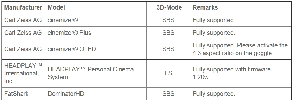
The following table lists the officially supported video goggles and head-mounted displays. As the Side-by-Side (SBS) as well as the Field-Sequential (FS) 3D video format is well established, it is expected that other video goggles claiming compatibility with SBS or FS video might be supported as well.
Additional Remark on FatShark’s DominatorHD FPV Goggles
Starting with S/N 1128 all 3D-cameras have an undocumented emergency feature for swapping left and right picture during camera operation. This helps to compensate for the occasionally swapped 3D-picture when powering-up the goggle. If you want to use this feature, simply create a short circuit between the nCTRL pin and the nearest GND pin on the camera’s extension port (see manual). During power-up, the NerdCam3D senses the logic level at nCTRL and, when a low signal is detected, the left and right pictures will be swapped. The short circuit does not have to be present all the time, it can be released after starting the camera. The camera keeps this setting until the next power cycle. If unconnected, the pin nCTRL is pulled high with a pull-up resistor.
In order to test whether your goggle is affected by this problem, simply connect the NerdCam3D to the goggle (either directly or via your AV video link), switch the goggle into 3D mode, and test whether the picture of the NerdCam’s left lens appears on your left eye while covering the right lens with your hand. The “left lens” is the lens on the left side when you try to read the textual descriptions and product name on the back-side of the camera’s PCB.