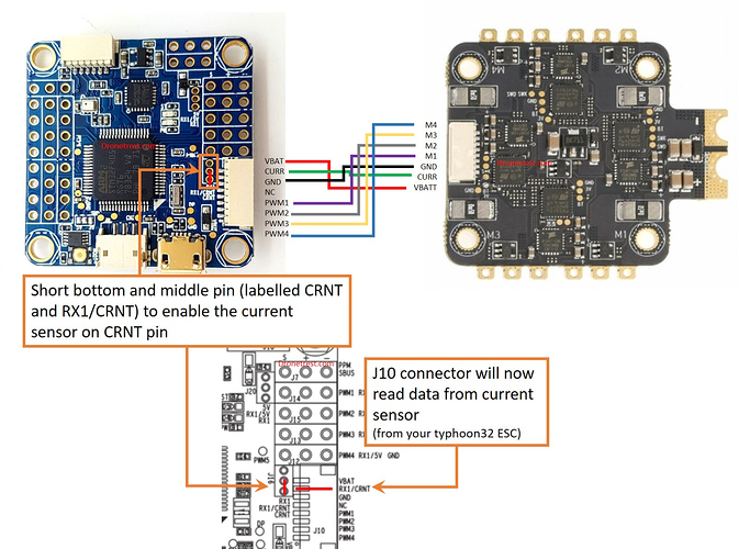
Hi I have been reading the tech write up for hooking up the omnibus f4v5 from unmannedtech. It has helped me a ton but I just had a couple questions. I am going to use a racerstar rev35 4in1 esc. So my fc hookup is going to use the j10 connector directly to my esc. I am going to solder bridge to set it up for crnt sensor. My other connections which I understand (I think) is connecting my receiver using sbus to J7. That leaves me powering the board battery power to the J4 J5 VBAT pads. The last part I’m a little confused by. The vtx and camera connections I didn’t understand from the guide. If i solder bridge J3 5v-RAM does that than put 5V on J17 and J18 center pad? So I could just run my vtx and cam using those 6 pads being powered by the RAM pad that now has 5 volts on it ? Or am I misunderstanding the ram pad?and if I am missing anything else please let me know
Also one other dumb question just because I’m setting up j10 for current that doesn’t mean my osd won’t show battery voltage correct? I’m assuming the osd chip has that information from board power?
