Some of the older APM modules have a tendency to burn out. However if you feel that this has happened (you dont see any lights on the board when you plug it in), read below on a possible way to fix it.
If you purchased your APM2.5 board recently you will probably not have this issue as the new boards have been modified to avoid this problem!
The Solution
NOTE: I’m assuming no responsibility if you destroy your board, if you are fine with that, read bellow
There are 2 different components that could have been fried, first one is a diode and the second one is a fuse.
In my case, the diode was fried and I took another smt diode from an old computer mother board and replaced the one on the APM.
The diode it’s there for reverse polarity protection, and if you don’t have one to replace it, you could just solder a wire to bypass it. The fuse is there to limit the current to 500mA.
Let me explain to you how you’ll find out which of the two components it’s the problem.You’ll need a multiplier for this.
Measure the the voltage between GND and point A (I marked on the APM 2.5 picture bellow). You should get 5.3v. That means that the juice gets to the reverse polarity protection diode.
Now measure between GND and the point B.
- If you have 0v, the diode is fried.
- If you have 1.3v, the diode is fried.
- If you get 4.7v or more, the diode it’s good
. If you get 4.7v
or more, you have to measure the voltage after the fuse C. If you get
0v, the fuse it’s fried.
If the found out that the diode is fried, you can plug the power module into the APM board, and with a piece of wire short the two terminals of the diode, the APM board should start up (that proves that the diode was actually fried).
Same goes for the fuse, if you found out that the fuse it’s the problem, you can short the terminals with a wire, the board should start right up.
Be best fix, it’s to find replacement components for the fried components and replace them. But -on your own risk- could just take them out of the equation by replacing them with a wire. You need ANY smd diode, you’ll find lots on an old computer motherboard.
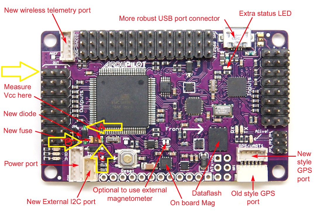
The “new diode” it’s the diode that got fried on my board.
The “new fuse” it’s the brown component between point B and C.
More info at here
