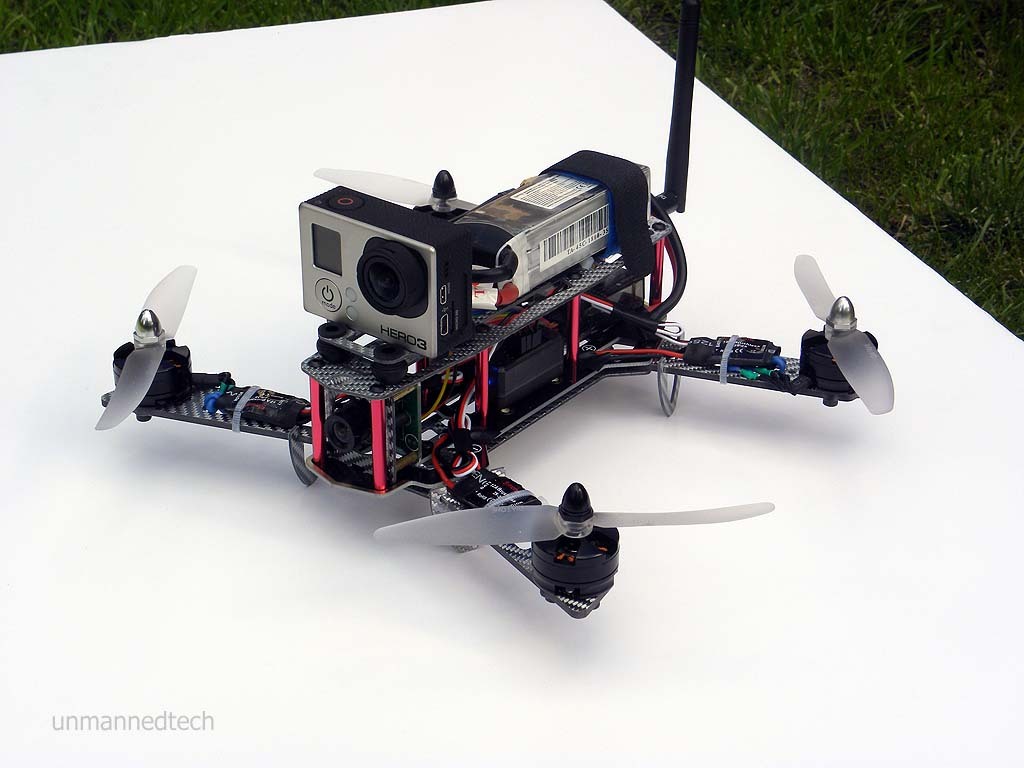
This is a quick and easy beginners guide to building a complete FPV quadcopter. In this guide we use the Silver Blade #37 as this is a nice piece of kit to get started with as it comes with all the screws and accessories you need for the frame build itself. We’re using this specific frame as an example, but all the techniques and steps outlined in this guide can be applied to almost all other mini racing FPV quadcopters (they all have a frame, four arms, four ESCs and four motors after all).
What We Used
Before we get started, here is a list of the equipment used in this build:
- The DroneBuildr tool kit - before you start, it’s a good idea to have all the tools you will need to complete the build; this is a great little kit that has all the tools needed (minus a soldering iron).
- The Silver Blade #37 frame kit - as mentioned above, this is a great little kit that has all screws etc. for the frame build.
- The Mini Quadcopter Motor/ESC combo pack - which includes four MT2204 motors and four 12A ESC’s designed for use on mini quadcopters.
- Flip32+ Flight controller - this is the ‘brain’ of your quadcopter. It controls all the components of your quad and we chose the Flip32+ as this is an easy to operate, quality flight controller. It has extra sensors like a pressure sensor and compass which improves performance and makes the quad easier to fly.
- 5030 plastic propeller pack - these are suitable propellers for the motors in the Motor/ESC pack used.
- TATTU 1800mAh LiPo Battery Pack - we used this battery as it is from a high-quality manufacturer (Tattu - one of the market leaders in batteries) and it is a perfect mini FPV racing quadcopter battery.
- EMAX Sony 811 700TVL CCD Video Camera - this is your standard FPV camera but with a fairly high resolution (700TVL).
- FT951 5.8GHz 22Ch 25mW mini Video Transmitter - this is the device thats transmits the video signal down to your monitor/goggles and this is a great choice for an FPV quad as it’s small and lightweight.
- The R9D RadioLink radio receiver - Unmanned Tech will soon be stocking these receivers. This is the device that receives the signal from the radio transmitter that tells the quad what to do - it’s quite essential to include this!
- A flight controller to receiver cable bundle - this is the cable that connects the radio receiver to the flight controller.
- 10cm long male XT60 wire - you need to solder this onto the power distribution board (which is in-built into the Silver Blade frame that we use here) in order to power the whole system.
- A bunch of accessories are also needed to complete this build and to make things tidy. For example, you’ll need a 20cm Velcro strap to secure the battery (we also used a bit of normal velcro), some zip-ties to secure the ESCs and we also used some black electrical tape for tidying. You will also need access to a soldering iron (and some solder) and some heat-shrink.
So that’s all the kit we used on this specific build and this can, of course, be applied to various other frames and variations on the kit can be used.
Building the Base
So let’s get to the build. Firstly, you need to get your frame up and running to some degree. The Silver Blade #37 used here has a bottom plate, the integrated PCB board and the arms and so we construct these first. The arms are wedged between the bottom plate and the PCB board as shown here and you secure them with the screws and nuts provided in the box. We then have the base on which we can begin to attached the ESCs and motors. There is no need to attach the red aluminium standoffs and the upper plate just yet.

Motor and ESC Installation##
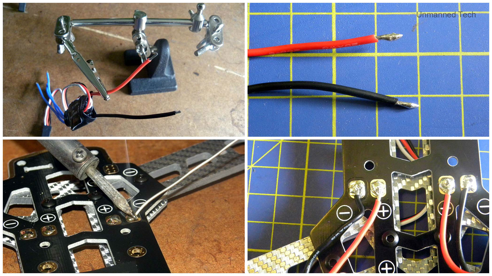
Once we’ve done this, we move on to the ESCs and motors. Now, to complete this part of the build you will need to do some soldering. For this particular build, we solder the ESCs to the inbuilt PDB directly and we have to solder the ESCs to the motors themselves (they do not come with bullet connectors). Please note that you may need to customise the length of all the cables on your ESCs so that they fit on your quad nice and neatly.
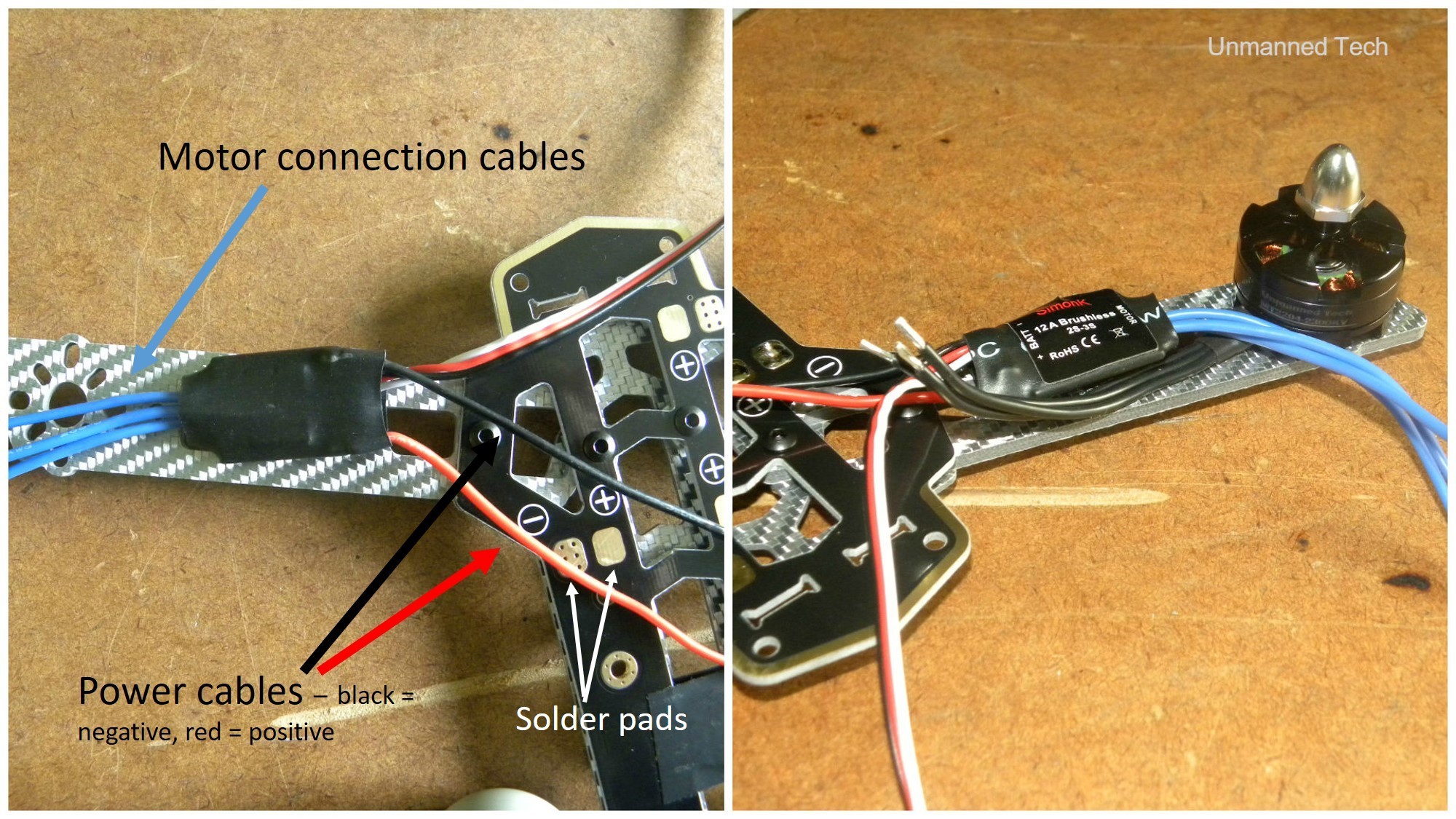
For example, we recommend that a good place to put your ESCs is on the arms of the quadcopter. After just placing the ESCs on the arms where we would like them to be, we can see that the power cables are far too long to attach nice and neatly to the pads provided on the PDB. When we also place the motors in their place on the arms, we also see that the cables connecting the ESC to the motors are also too long. Customisation is therefore called for. We cut the cables to the appropriate length, and get on with soldering.
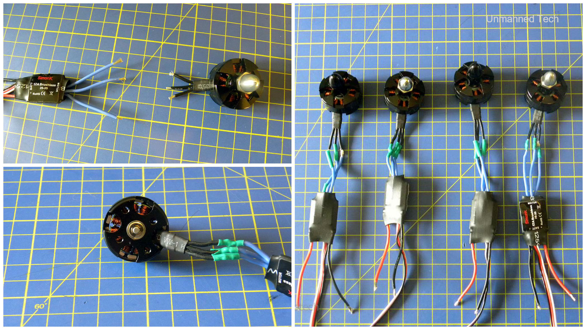
We first attach the ESCs to the motors. Now, for every quadcopter, you have two counter-clockwise motors and two clockwise motors. You will have to look at the manual for your flight controller to find out where each motor should go, and since we used the Flip 32+ here, we follow the instructions given in the Flip32+ guide. There is also a very precise order to which ESC cable connects with which motor cable, depending on the orientation of the motor in question. You can see a detailed guide on how to do this in the ESC to motor connection guide. You then solder the cables together (not forgetting heat-shrink) to the appropriate length (please see the soldering guide for help). When cutting the cables down to size, please be careful not to cut all the way down to the ends as this will inhibit the soldering process. It does not matter if you have some excess cable, as this can be tidied up later.
We now have all the ESCs connected to the motors (correctly let’s hope) and we can now solder the ESC power cables onto the in-built PDB. Again, make sure to cut the cables down to the right length before soldering (see please the soldering guide for a detailed description on how to do this). Please also pay special attention to which pad you solder which cable to i.e. red = positive and black = negative … this is very important.
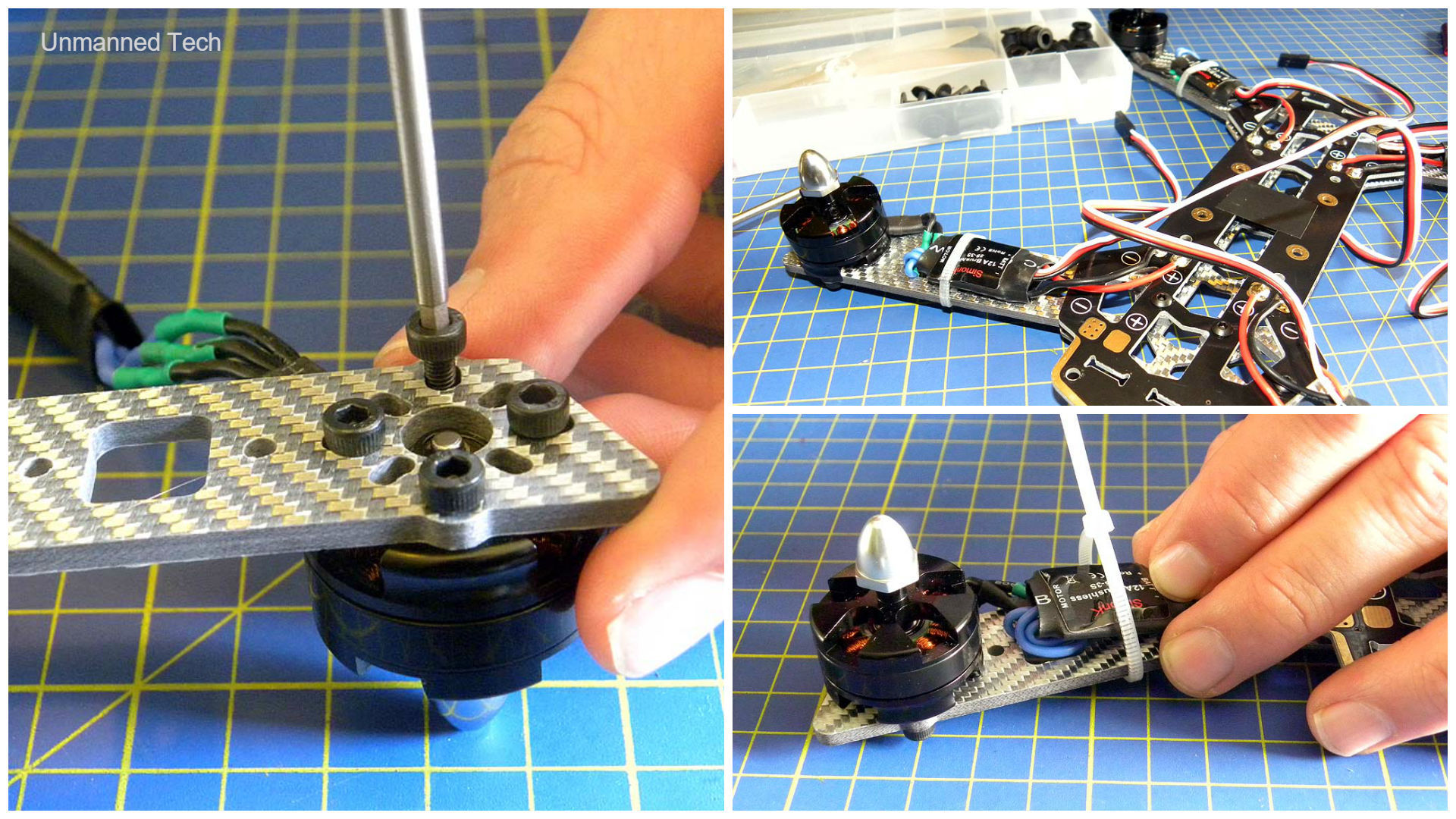
So we have all the ESCs soldered onto the board and connected to the motors. Now we attach the motors to the end of the quadcopter arms with the screws provided in the motor packs. It is useful to position the motors in such a way that the wires point down the arms (as much as possible), as seen in the pictures. The excess cable that you may have can therefore be tucked under the ESCs, and the ESCs can then be secured with zip-tie.
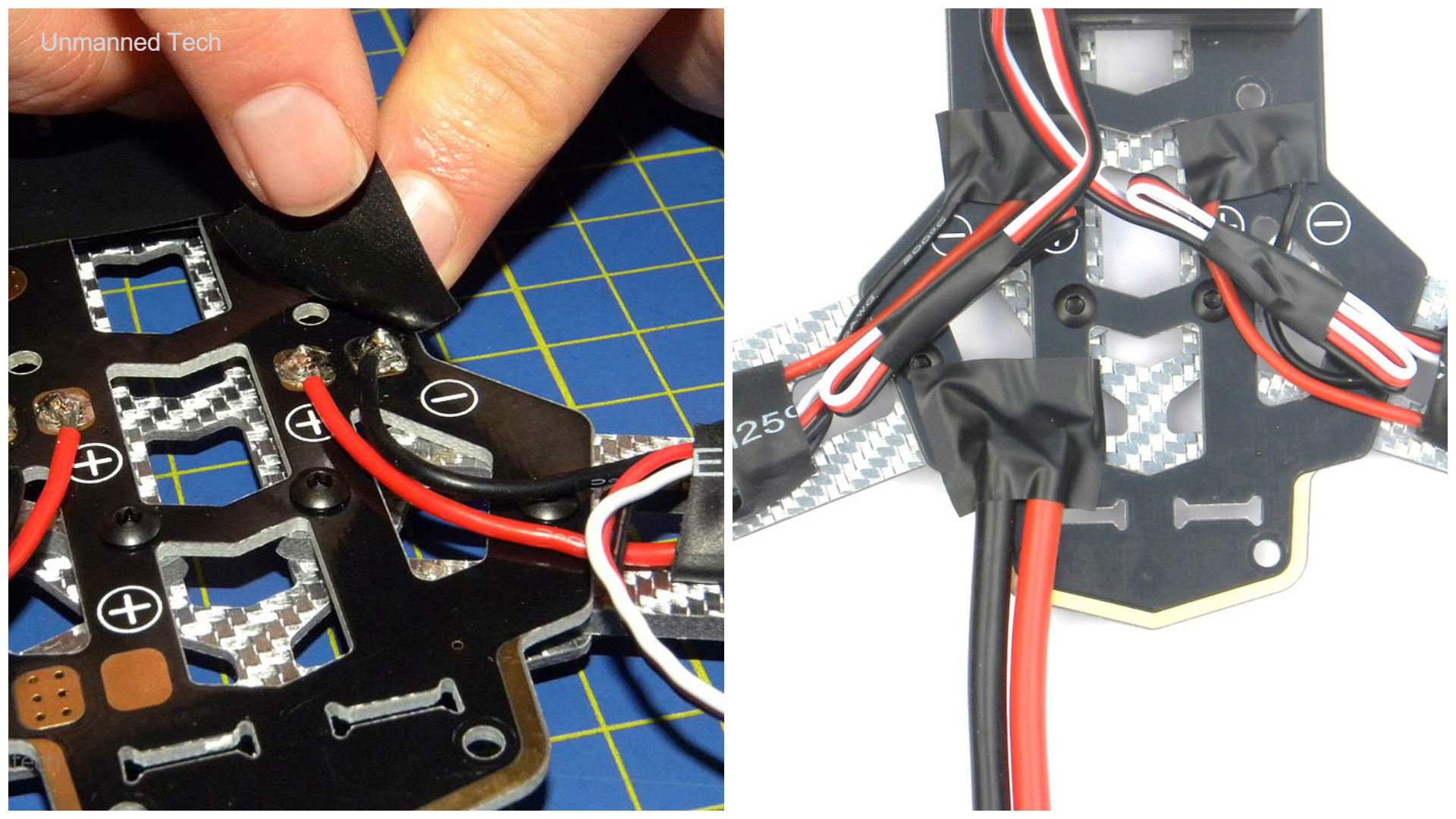
Right, so we have things moving on somewhat. At this stage, it would be a good idea to also solder the male XT60 10cm wire onto the PDB of your quadcopter (this is to connect to the battery). Please note that we used this cable (with this connector) as we are going to be using the Tattu 1800mAh LiPo battery which has a female XT60 connector on it. We therefore need a male XT60 connector for obvious reasons. I.e. what I’m trying to say here is please check which connector your battery comes with and what power cable you’re soldering onto your board. This power cable should be soldered onto one of the pairs of positive and negative pads on the PDB. The battery connector (the male XT60 wire) can be seen in the right of the pictures below. It is also a good idea to add some electrical tape onto the soldering joints to ensure against short-circuiting the system, but also to make the whole quadcopter look neater. We also wrapped the servo cables on the ESCs in black tape to tidy them up.
Flight Controller Installation##
So now we move on to installing the flight controller onto the frame. Now, all flight controllers have an orientation and so it is important that you secure it to your frame facing the correct way (this saves a lot of a hassle later). Specifically for the Flip32+ board that we used here, the USB port is the back of the board and the opposite side is subsequently the forward facing side. You therefore have to place the flight controller so that the forward facing side is pointing in the same direction as the front of the quadcopter (for the Silver Blade #37 there is no specific ‘front’ so you can choose).

We secured the Flip32+ here with 3M mounting foam to the middle of the quadcopter (facing the correct way) and then we proceeded to plugging in the ESCs. We use the servo cables to plug the ESCs in (the black, red and white cable) and these plug into the output pins of the flight controller. This is because the flight controller outputs information to the ESCs to control the speed of the motor. According to which flight controller you’re using, each motor is numbered 1 to 4 in a specific order (as mentioned above). You need to plug the ESC connected to motor 1 into the output pin labeled 1 on the flight controller, the ESC connected to motor 2 into the pin labeled 2 etc. You also need to plug the servo cables into the pins in the correct orientation. The three coloured wires in the cable (black, red and white) correspond to ground, voltage and signal wires respectively. You therefore need to ensure that the ground wires are connected to the ground pins, the voltage wires are connected to the voltage pins and the signal wires are connected to the signal pins. You can see this demonstrated in the pictures above. Most flight controllers will have the pins labeled with which pin is ground, which pin is voltage and which pin is signal. For example, in our Flip32+ guide, you can see that the pins are labeled with G, V and 6 (the 6 is for motor 6 but this is the signal pin).
Connecting the Receiver
We now connect the remote control receiver (the R9D RadioLink receiver in this case) to the flight controller. This is connected to the input pins on your flight controller, as the flight controller is receiving information from your radio control on the ground and inputs this into the flight controller. We connect the two using the flight controller to radio receiver cable as shown in the images below.
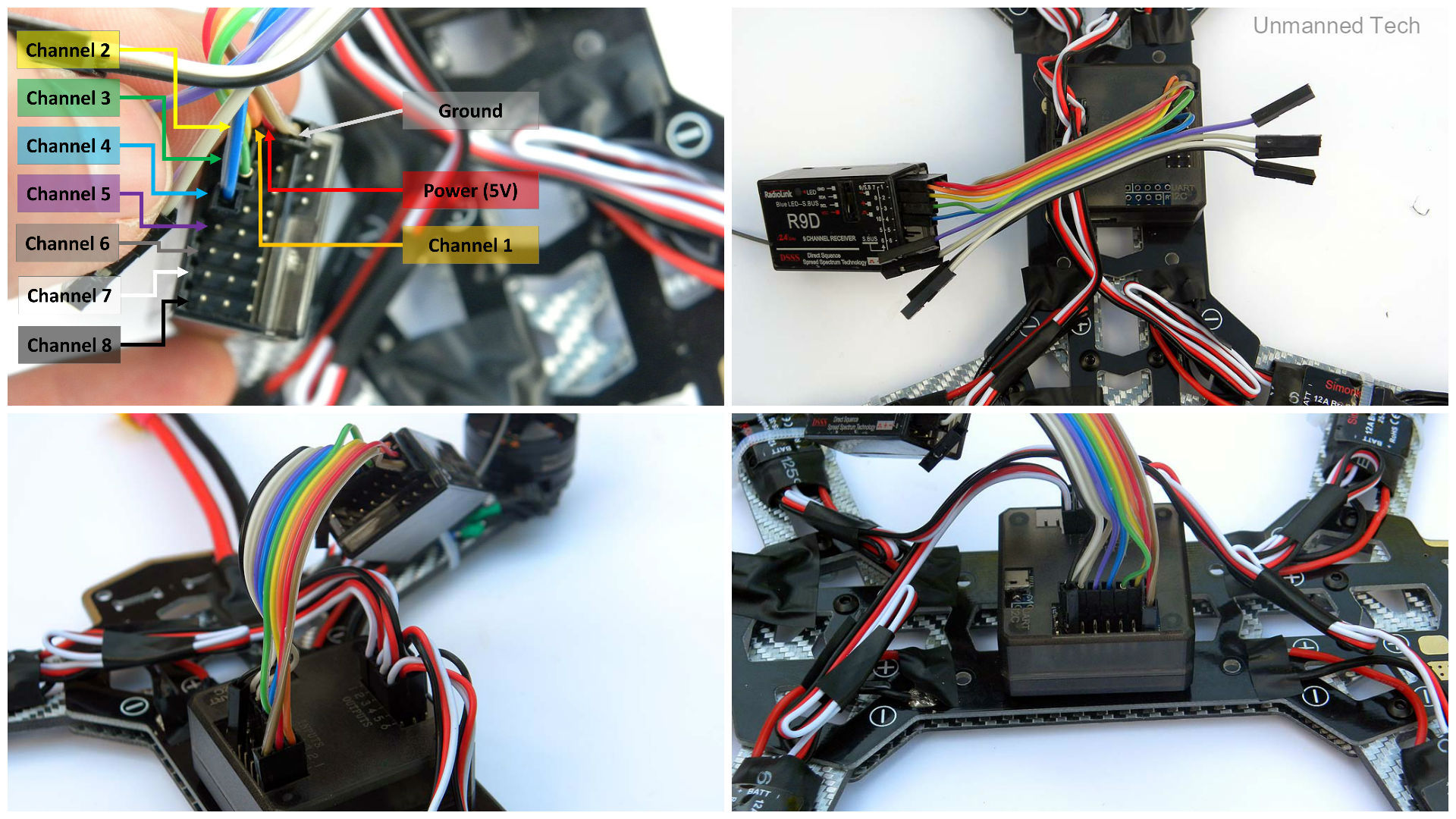
The cable that we suggest you use here has 8 separated cables. The first one is a combo of 3 wires (brown, red and orange) which consists of a ground wire, a power/voltage wire and a channel wire. This first powers the receiver but also provides a channel input. The rest of the wires in this cable are then the other channel wires, as you can see above. Now, each channel controls a function of your quad. For a racing quad such as the one we’re focusing on, you only really need 5 channels. Channels 1-4 are the basic pitch, roll, throttle and yaw functions and you generally should have a fifth channel to change flight modes (i.e. accro, stabilise etc.). In the picture above you see all the channel wires connected but this is not necessary for a FPV quad. Please note that you must plug the cables in the correct orientation i.e. in the channel pins of the receiver.
The FPV System
We next focus on the FPV section of the build i.e. setting up your camera and transmitter combo. This step is a bit tricky at the moment and needs some explaining. If you’re not familiar with soldering this may take a while and there are a few items that you need to source for this setup. Please note that Unmanned Tech will soon be selling a complete FPV bundle product that will include a camera, transmitter and all the necessary cables so that all you need to do is plug everything in. However, at the moment, you need to make one yourself.
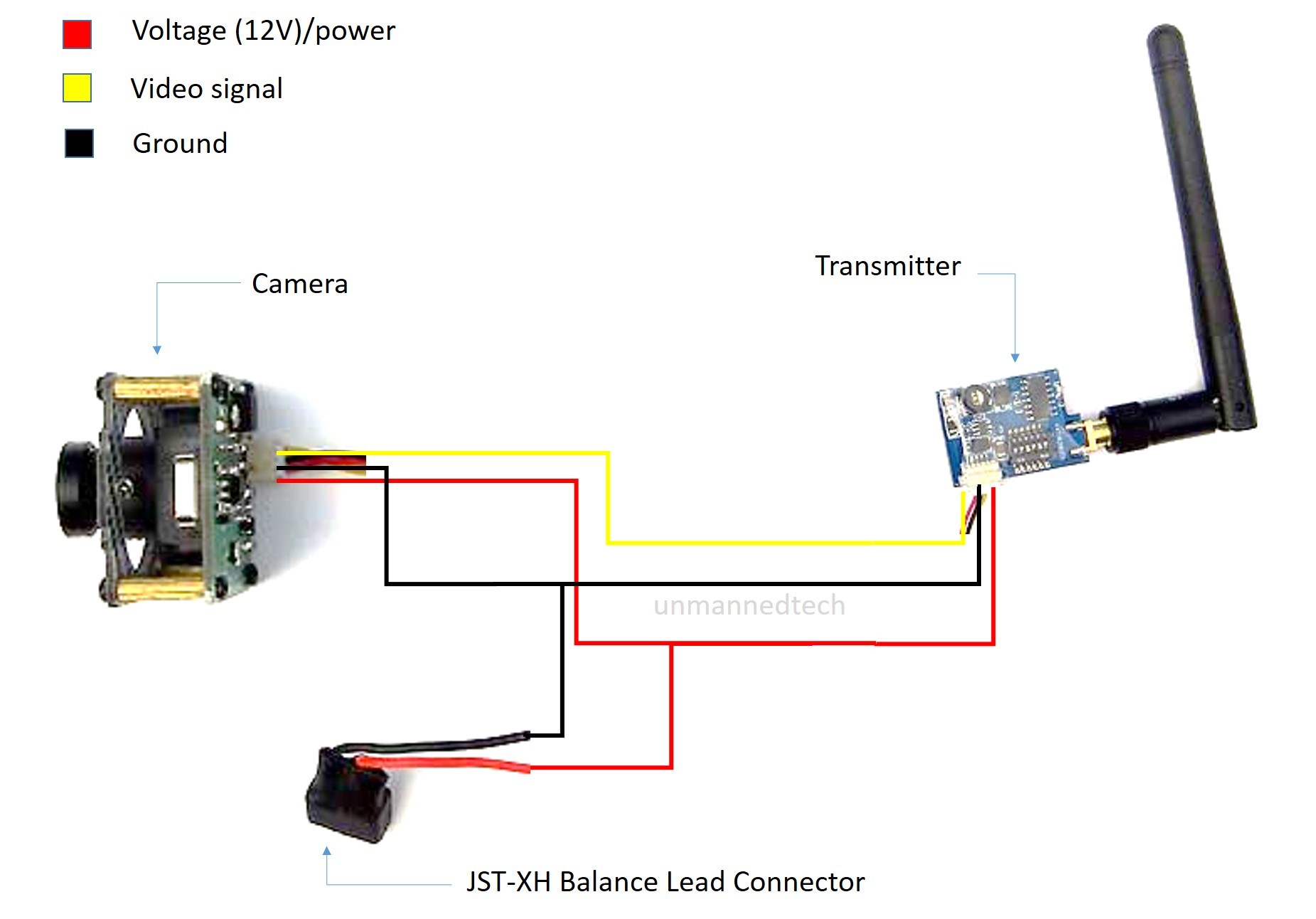
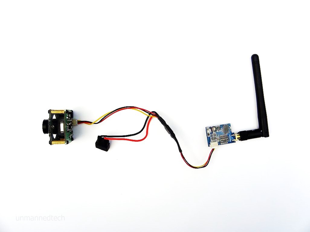
The diagram above shows how you set up the entire system. There are several different options for how to do this, but we decided on the above in this case. We therefore connected the voltage, signal and ground cables from the camera to the transmitter, and also connected a balance lead connector in order to power the system. This connector is a JST-XH connector as highlighted in the picture. The cables needed to do this come from the cables that are included in the camera and transmitter packs, some spare wires to connect the balance lead connector, and the connector itself. We also used heat shrink on the connection to neaten things up. The finished result is below and we have our FPV system.
The Final Stage
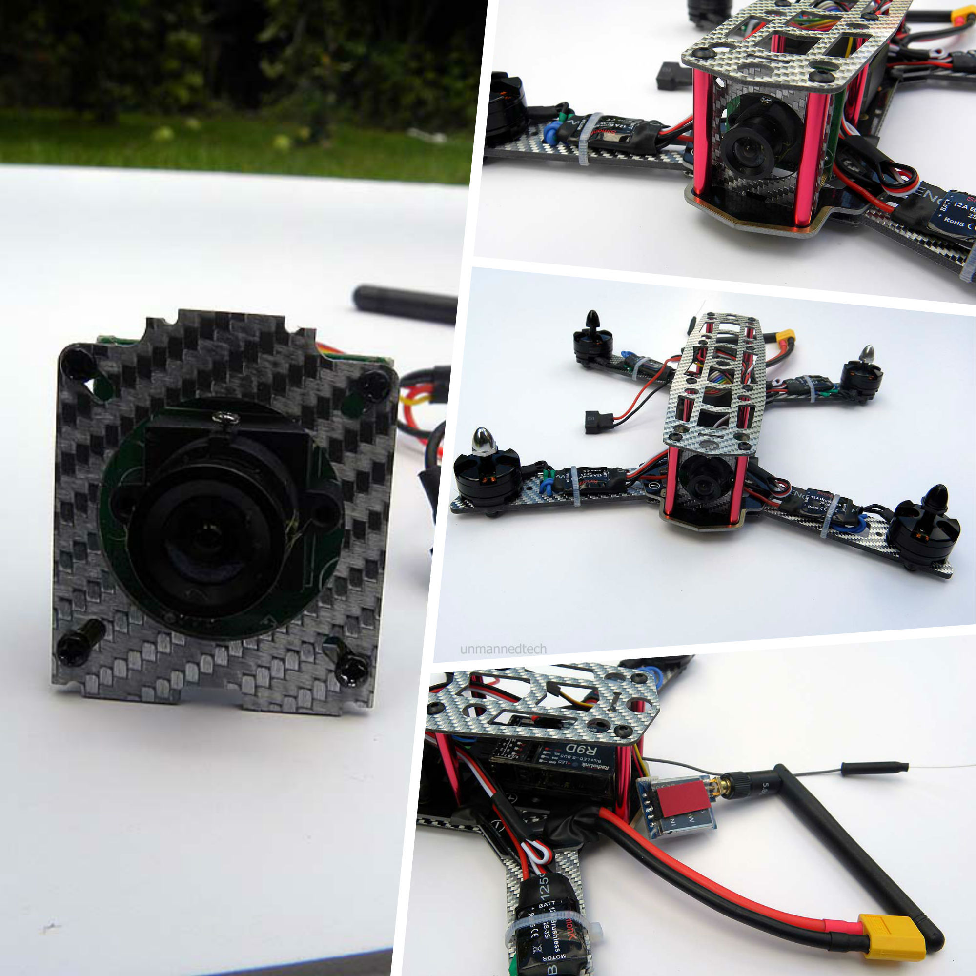
We now enter the final stages of our build (exciting!) and all we need to do now is to secure everything to our frame. Let’s start with the FPV gear that we have just connected. The camera needs to be attached to a mounting plate that should be provided in your frame kit; it certainly is for the Silver Blade kit that we are using here. Once this is attached, this plate then needs to be sandwiched between the bottom plate of the frame, and the top (yet to be attached). The top plate of the frame is connected via the red standoffs to the bottom. You can see how this is done below. We also attached the transmitter to the far side of the quad with sticky mounting foam as seen. As extra security, it is always a good idea to secure what you can with zip-ties as well as any mounting foam. We therefore did this for the transmitter once we have attached it to the underside of the top plate. Please note that all the cables connecting these two were threaded through the quad inside the standoffs.
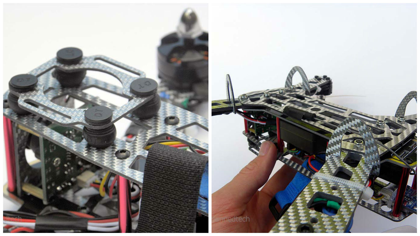
At this point I then attached the mobius mount (that was supplied in the frame kit). This is an optional addition for any FPV quad that allows the user to add a second camera onto their frame for picture and video taking (when the original camera is solely for goggle/headset use). This is simply done with rubber vibration dampening balls (and locks) and you then have a platform for your second camera (usually a GoPro). You can then slot the landing legs onto your frame (this can be done at any stage).
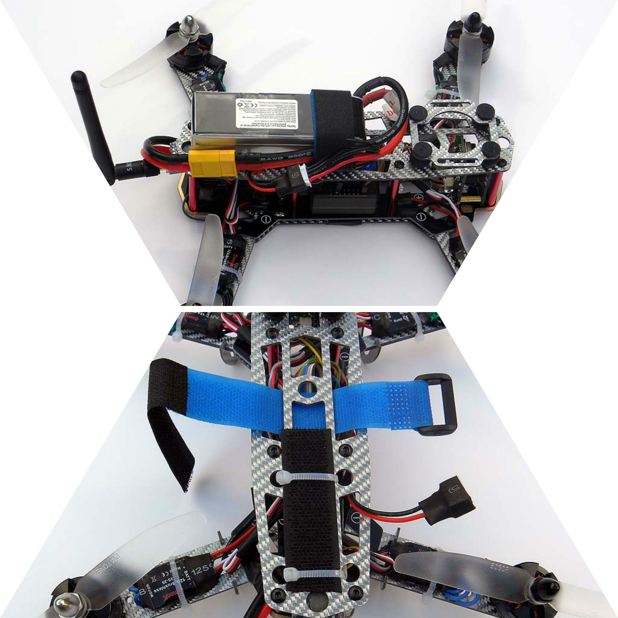
We then install the TATTU 1800mAh LiPo Battery Pack onto our frame. There is no set place on any frame for the battery to go and so this is free for you to choose to best suit your arrangement. In this build, we positioned the battery at the back of the top plate, as this was the logical place. Now, it is fairly essential for the battery to be pretty secure on your quad, and so we secured it with both sticky velcro, and a velcro strap. On top of this, we also secured the velcro on the quad with zip-ties, as we know the velcro can easily become unattached when taking the battery off. Please note in the picture below that the balance lead connector of the battery was positioned close to the connector on the FPV system so that it could easily be plugged in. In the pictures below you will also notice that we have added the propellers to the motors. As mentioned above, you have clockwise rotating motors and counter-clockwise rotating motors and so the correct propellers needs to be attached to the correct motor at this stage. You will need to consult the manual of your flight controller for the motor orientation, which will tell you which propeller to put on which motor.
In Conclusion…
And there we have it; a complete racing FPV quadcopter build. We have just gone through the physical build of this quadcopter and in order for you to get your quad in the air, you will need to setup and configure your flight controller. For this, you will need the manual of your flight controller. Please remember that we used the Flip32+ here which is a great example of a suitable flight controller for these purposes and is relatively simple to setup and get going.
Thank you for reading and I hope this was helpful. Please do not hesitate to leave comments/questions at the bottom of the page and I will get back to you on these as soon as I can.
P.S. anything you can tell me to improve this guide would be much appreciated. Thanks!