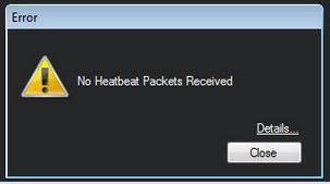
We had a customer that wrote to us about this problem that he experienced with his APM 2.6 board. It had been working fine for several months until suddenly when he tried to rebound his transmitter to his receiver, he was unable to connect to Mission Planner with USB, with a ‘no heartbeat packets received’ error. Strangely, he could upload and update firmware on the board through Mission Planner, but when it came to connecting though Mavlink to enter a flight plan, or change the configuration, he got the error. If you are experiencing similar problems, hopefully this article will help you solve them.
Are you using the correct board rate and COM port?
A common issue users have is not selecting the correct COM port or baud rate. If connecting via USB you will need to set the BAUD rate to 115200, and if connecting via a telemetry module the buad rate is usually 57600. If you are not sure connect your board via USB and select the following options in Mission Planner.
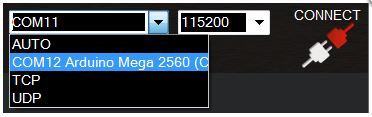
With the APM board connected via USB to your PC you must select the Arduino Mega 2560 board from the drop-down near the top right of Mission Planner, and select the board rate as 115200.
Reset the board to factory settings
The next thing to try is reset your board to factory settings and load the latest firmware. If you dont know how to reset your board then the best thing is to follow the guide below:
After that is done you can try to see if it works as most of the time when you receive the no heartbeat packets its to do with firmware not being correct.
APM Voltage Regulator Damaged
If you find that the above steps don’t work, but you had a board that was working and is not all of sudden. This is usually caused by a diode/voltage regulator that gets damaged somehow. The most common symptom of this is that you get bad gyro health errors on your HUD of the APM mission planner, however no hearbeat packets received could also be a reason. If you cannot connect to Mission Planner, you should verify the voltage regulator on your board. Using a volt meter, check the first and last pin of the I2C port and verify that the voltage output is 3.3 volts ±1. A useful video on how to do this is shown below:

If you discover that the voltage regulator is blown then hurrah! You’ve found out the problem! But what do you do about this? Well, if your board is still under warranty just contact the shop you purchased it from and they should replace it for you. If your board older and out of warranty then there is a relatively straight forward DIY fix outlined in the following video, but you will need some soldering skills to do this and I don’t suggest you try if you have not had much experience soldering: If you try this you do so at your own risk of damaging your APM board beyond repair!

I hope this helps some of you out there!