Pixhack Quickstart Guide/Manual

In this guide we will show you how to quickyly get started with your Pixhack autopilot. The Pixhawk autopilot is a variation of the popular pixhawk autopilot, and although it uses the same sensors, it has been re-designed from the ground up to make include a vibration isolated IMU for better performance. The Pixhack is fully compatible with APM/PX4 firmware stacks.

Pixhack Overview

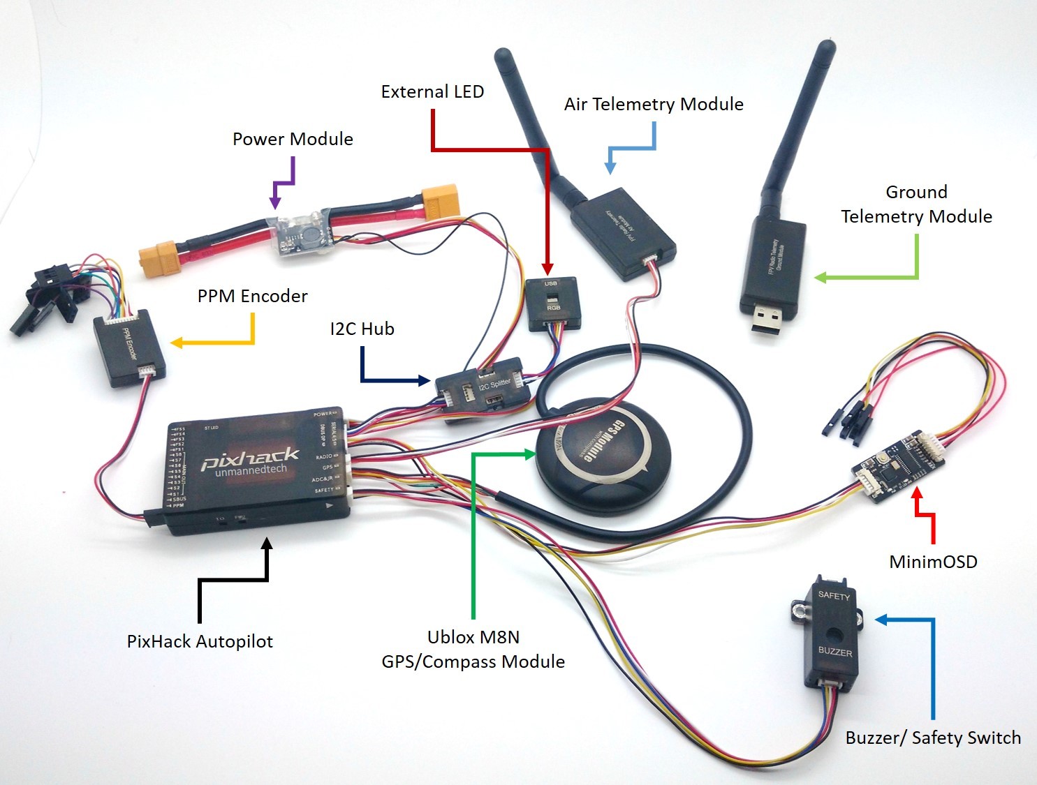
The great thing about the Pixhack autopilot kit that we sell, is that it includes all the accesories that you could possibly need. Each of these include a pixhack compatible connector. You can still use other accessoried designed for the original pixhawk, but you will most likely need to change the connector as the pixhack does not use DF13 connectors common with pixhawk modules.


The connectors are all clearly labeled and can only go in one way so you dont need to worry about connecting something upside down.

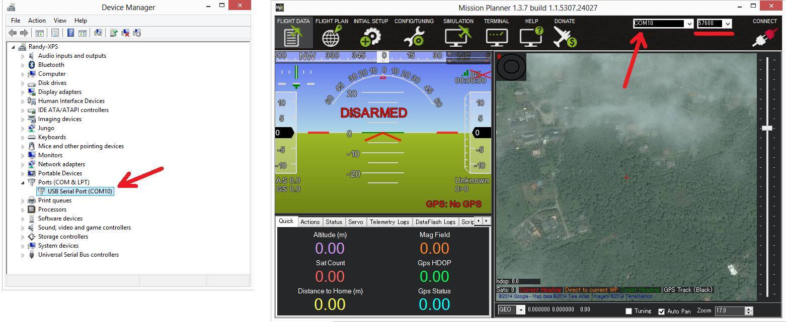
In terms of installing the firmware such as arducopter, you will just need to follow the same steps as you would for the Pixhawk/PX4 autopilot. Simply install mission planner and install the firmware onto the board, for full details please refer to the pixhawk wiki.

Autopilot Connectors

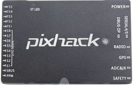
The main outputs S1-S8 correspond to pixhawk RC1-RC8 pins. The extra outputs FS1-FS5 correspond to pixhwak RC 9-RC13 outputs.

PPM- for SBUS inout
SBUS- for SBUS output
MAIN OUT- for main output ports S1-S8
FS1-FS5- for extension ports
POWER- for PM voltage and current module sensor. Do not connect the PM sensor to other port!
DBUS OP- for data extension including Telem 2 for MinimOSD
SERIAL4/5- for serial port 4/ 5
RADIO- telem 1 port to connect telemetry module
GPS- for GPS module and compass
ADC&JR- for ADC 3V3 output and JR transmitter input
SAFETY- for buzzer and safety switch

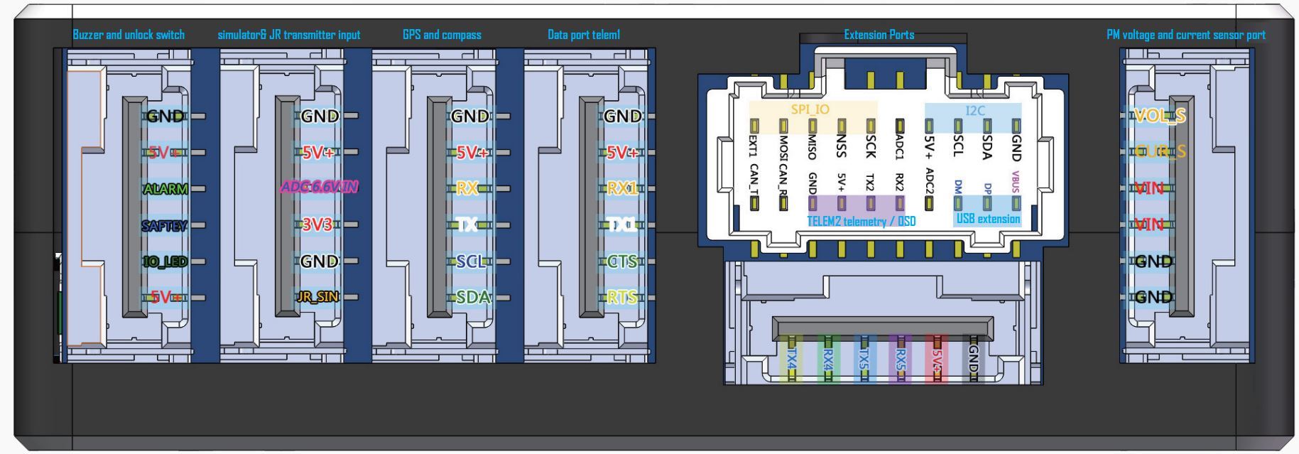
Here is the exact pinout of the interface connectors

Connecting your receiver

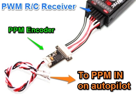
Just like the original Pixhawk, you need to use a RC receiver that is able to output PPM/SBUS signals for the autopilot to read. Either way the pixhack reads teh PPM input from your receiver via the PPM port. Many users get confused between the SBUS and PPM ports on the board, the SBUS is purely used for output so you should always connect your receiver to the PPM port.

If you want to find out more about PPM, PWM check out our guide by searing the guides category for PWM and PPM

However if you are using a R/C receiver that only supports PWM, the Pixhack kit we sell also includes a PPM encoder that will convert each of the PWM channels to a single PPM signal that will be read by the autopilot as shown below. The PPM encoder supports a total of 8 PWM channels.

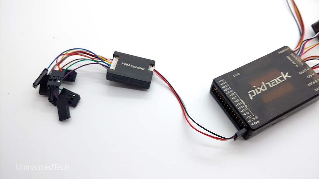
Start with the 3 pin servo cable for channel 1 on your Receiver which also provides power for your R/C receiver.

The PPM port on the pixhack provides 5V power for your receiver via the middle pin

Connecting MinimOSD

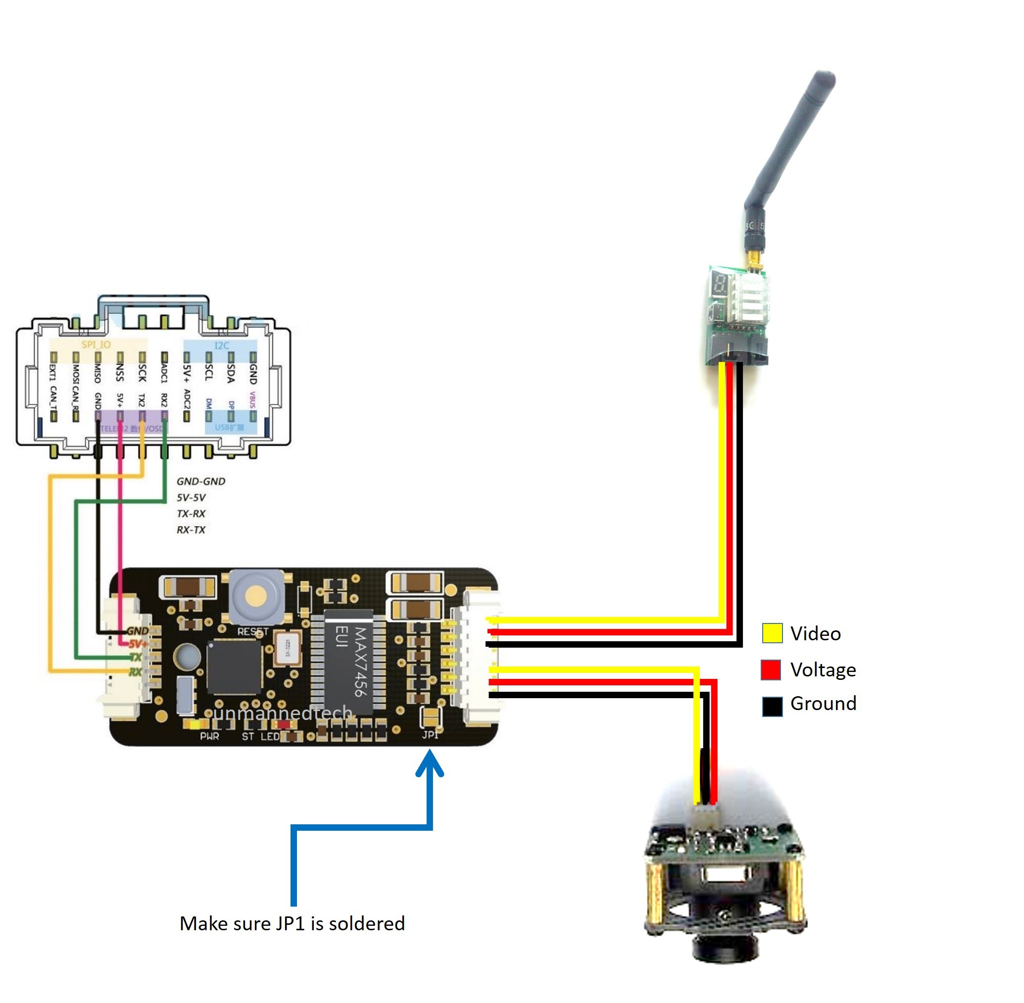
A minimOSD board is included with the Pixhack kit, and it allows you to to overlay useful information on top of your real time video feed. For more information on FPV, please read our FPV Guide You will simply need to connect the minimosd board to your FPV tranmitter/receiver according to the pinout as shown below. The minimOSD then connect to the Telem 2 port (DBUS connector) on the Pixhack.

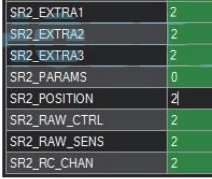
You will also need to change some settings within mission planner to enable the minimOSD board, To get here you will need to open mission planner, and go to the config>tuning tab, and view the full parameter list. You will need to change all the SR2_EXT parameters to 2.

Powering the output rail

The output rail on the autopilot is powered separately from the main pixhack (which is powered via the power rmodule). This does not really matter for most multorotor applications since ESC;s are powered via the PDB so the pixhack does not need to provide output power to the ESC’s. However if you want to use a servo you will need to power the output rail with a 5V BEC. In most fixed wing aircraft the ESC includes a BEC so you can use your ESC to power the entire output rail. Just be careful to ensure your BEC can provide enough current to power all of your servos.

Pixhack Schematic

Here is the schematic PDF for the pixhack autopilot should anyone need to know the inner workings for custom functions.

Pixhack-Schematic.pdf (600.1 KB)

If you have any questions or run into any problem in getting your pixhack up and running, please let us know by asking a question below.

I have asked the same question through Unmanned tech support, but thought it might be worth asking here in case someone else knows. What is the make/model of the “new” connectors? I have not been able to find any information online and I was hoping I would be able to work it out when my Pixhack arrived, but there are no markings on the connectors to help.

@Chris_Gent sorry about the delays in getting back to you, the connectors used on the pixhack are 6 pin JST GH1.25

These connectors used on the pixhack are not very common indeed but I do like them as they are super easy to plug in and unplug, but very secure at the same time :smile:

Thanks, any ideas about the 20pin connector?

Hi ! It’s all too pretty but I found problems in this board.
I think the output pins FS1 to FS5 are there for nothing.
At same time that part of rail section it seems to be independent in power so
only the S1…S8 is powered up with the ESC.
I give up to connect a gimbal on RC9 or RC11 on this rail. Need only tilt on cam but I gave up to try with this FC.
One FC with a rail with 5 output pins doing nothing I don’t need. Several manual is referring these pins as " not defined yet".
So if some one knows any solution I would like to hear.

Is this still so, or was a solution found, if it is the Pixhack will not work for me.

Hi again.
First Pixhack burned after I did a mistake (connecting power to the wrong pin),
So many trials I did that was previewed a accident.
I bought a new one, this time on Ebay , same version and I connected the gimbal.
The FS rail still have no power. To connect something there you must power up the rail in use.
I connected the gimbal to RC9 and in radio the F7 button. With the Mission Planner I made all setup
but for me I can’t use it because I couldn’t control the gimbal to stop where I want.
Or in front, or all up or all down. He don’t stop between the higher and lower points. So I decided to connected
to my radio and Devo RX1202 receiver.
About the FS rail pins: I think the newer version is already working but as I said you can allways power up the rail in use and he works.
Abour this FC tests : I can say anything yeat because I buid a 500 quad with this board.
In the end, the model weight was excessive hight (1950 grams with gimbal and battery) for a 4 poor motors Turnigy MT2213 935KV. He lift but needs more juice.
I need to find a solution.

Thanks for the detailed explanation. I will crack on with the Tarot 680 Pro build testing as I go.

Are there instructions anywhere on how to program the MinimOSD included with this kit?

There is some basic details on the arducopter wiki. All the software stuff is the same, but the pixhack just has diffent locations of connectors as the Telem 2 output is located on the big 20pin connector.

Thanks for the link. Am I right in understanding that what is shown or not shown in the on screen display is controlled via mission planer rather than using external software to program this?

If you download the latest minimOSD firmware, the OSD config tool is included within the zip file. Pixhawk just sends data via the telemetry port but you choose what you display including where and how via the OSD config tool. To be honest the development has slowed down abit on the OSD side of things since most of us display the telemetry info via mission planner/Tower on the phone and keep the video feed clear. So the latest release of MinimOSD extra for pixhawk is not the most user friendly version as ony FPV racers use OSD. We will also soon see digital video transmission systems soon which include the telemetry info in the actual data feed making an OSD device redundant.

Thank you, I have decided to use a Teensy LC board to transmit telemetry direct to my Taranis.

Do you use the standard stick antenna on your 433 mhz and Tower.

Yes the stock antenna with the telemetry modules should be fine for about 1-2Km line of sight.

I want to buy another Pixhack for a fixed wing, do you have in stock an interface with the relevant leads so that I may easily program the MinimOSD board?

yep we do have them in stock right now, and to program a minimosd you will need to add an FTDI interface, but thats out of stock right now :frowning: we should get some more FTDI boards in about 3 weeks.

hi when i download the flightplanner it asks what com port im useing . what comport do i select for the pichack many thanks

whats the recomended spektrum reciver to use with the pichack?

Hey, the company port you must select depends on your PC. As a general rule is the highest number, but the best way to see is to go to your device manager and see which COM port number is assigned to the pixhawk board

As for a spectrum receiver I would suggest a satellite receiver, I believe that DSM-X or DSM-2 receivers are supported.

As a developer on both ArduPilot and PX4 software project priseborough (Paul Riseborough) · GitHub, I get to see a lot of user data logs. Please be aware that the inbuilt vibration isolation of this board can hit a resonance at certain prop and motor speeds which results in loss of inertial navigation and potential crash or flyaway. Please ensure you take the same care mounting this board that you would with a Pixhawk (use soft foam pads).

1 Like