Thanks for all the information on here, I just have one issue using the Typhoon V2 4-1 ESC and Omnibus F4 V5. The current is only displaying 0.3-2 amp even at full power. I have selected J16 middle and bottom jumper.
Lowered the current scale in beta flight not helped seems as it’s the range of current not displaying.
Is the current sensor setup different as I heard it’s digital ?
I think we have been helping you over email.support about this, but once we work it out I will update this post to help anyone else out who might have a similar issue.
Possible reasons:
ESC not connected correctly
battery leads not connected to current sensor correctly
current sensor not calibrated (you already said that you tried this so just adding here for someone else)
After flashing betaflight 3.3 the problem is still here so I decided to use ESC telemetry instead of the inbuilt current sensor on the ESC. This is working now and showing a full range of amps. I don’t know but is there something that needs changing on the Typhoon V2 4-1 ESC to output current instead of ESC telemetry?
Just one more problem do you know how to adjust the calibration of ESC current in betaflight as the adjustment does not show on the configuration page on betaflight when in ESC telemetry mode?
As far as I recall you don’t need to change anything on the typhoon ESC to enable.regular current output… but I will check with the designer…
To calibrate the individual esc current sensors you will need to do this within the blheli32 suite (you can connect via passthrough). I read in December 2017 that the Devs will be adding this feature to blheli32 but not sure if it has been added yet.
Hi Alex, me again! It would be most helpful to have the location of the UART’s marked on the pin out guide. UART 6 is but none of the others are. Also, can you explain how and where to connect a bluetooth transceiver to the v5 board.
I have the same FC but dont seem to be able to get my crossfire working on J6 TX6 & RX6. I am using TX1 and RX1 for GPS and TX3 and RX3 for my compass so was hoping to use J6.
Hello,
i have the Omnibus F4 V5.1 and the Typhoon32 V1.2 connected with the 8-pin-cable.
As rx i use a Spektrum-Sat on UART1. On J16 i have bridged the lower and the middle pin to see the current from the Typhoon.
But nothing displays, when i switched in “Power&Battery” to "ESC Sensor.
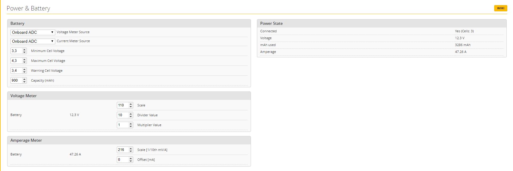
With “Onboard ADC” it shows 48 Amperes when the motors still stand.
Has anyone an idea what i can do to show the current from the Typhoon ?.
Sorry for my bad school-english, it was 40 years ago ;).
Greets,Michael
Have you gone through the current sensor calibration? There are a few ways to do this, but the safest way to get a good estimate is shown in this video: (the beginning of it is just talking, information starts at around 2:25.
Otherwise another way to do this is to measure the value of the resistor next to the actual current sensor resistor on your FC and then you can calculate what the scale/offset should be as discussed in this RCG post
There is also a third way to attach a Watt meter to your quad and measure the current when motors are running and then adjust the current, but you need to be careful when doing this as it can be quite dangerous since you are throttling up your motors with propellers while its resting on your desk!.
Hello Alex and thanks for your answer.
Maybe i had tell it wrong,i am sorry for that.
My problem is not the wrong display of the current from the FC.
I have connected the Typhoon with the F4 as you wrote in your Blog in the Part
“Powering from 4in1 ESC using current sensor”
This configuration lets you use the built-in current sensor on the typhoon 4in1 ESC (or any other 4in1 ESC that has a current sensor).
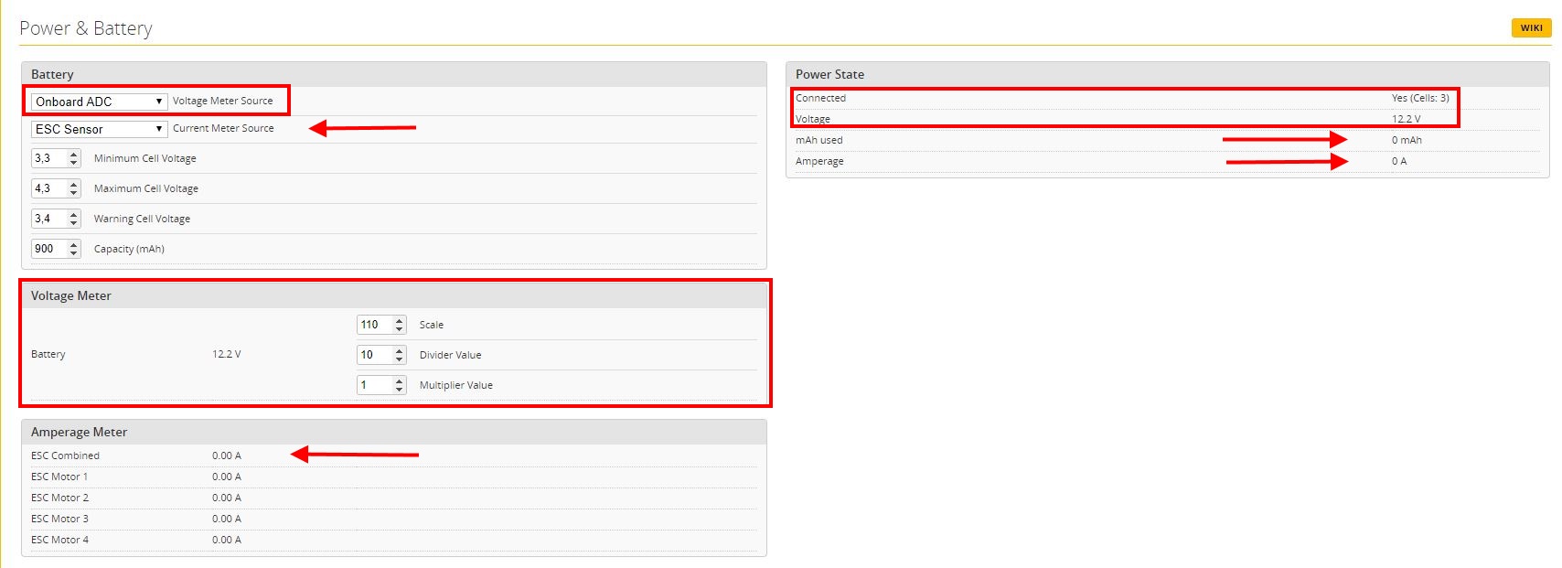
Now i want to use the current sensor from the Typhoon (second pin on J10 of the F4), but nothing displays when i choose “ESC Sensor”. Also there is nothing to calibrate when in choose this.
In the rectangles you can see the correct values of the voltage-sensor from the FC.
The arrows marks the values from the esc-current-sensor. There is no field to calibrate the sensor of the Typhoon. It does not matter if the motors turn or stand, the values are always the same.
It looks, the Typhoon gives no data from his current sensor to the Omnibus F4.
On J16 i have short the bottom and the middle pin.
Do I have to adjust something else in betaflight?
Thanks in advance, Michael
Hi there.
I want to use the Flight controller for a plane but for some reason i’m no able to connect the servos into the pwm 1-4 to work. I use betaflight to program but no luck so far. Every place i turn it seems that this board only works in drones and not in planes. Is there any link i can use or pdf to program the flight controller for a stabilized flight?
Hey Stedyman and Alex,
I encountered the same issue. Turns out, the Typhoon V2 doesn’t seem to provide the analogue current sensor data on the 8 pin plug anymore but (digital) ESC telemetry instead. So I am trying to get it working with J16 soldered to RX1 right now. Your low amp reading is the current coming through the FC only - the omnibus has a current sensor built in as well.
Thanks, Unmanned, Hope you’re getting a kickback from Airbot or company. As you have the only reasonable documentation on the on their hardware.
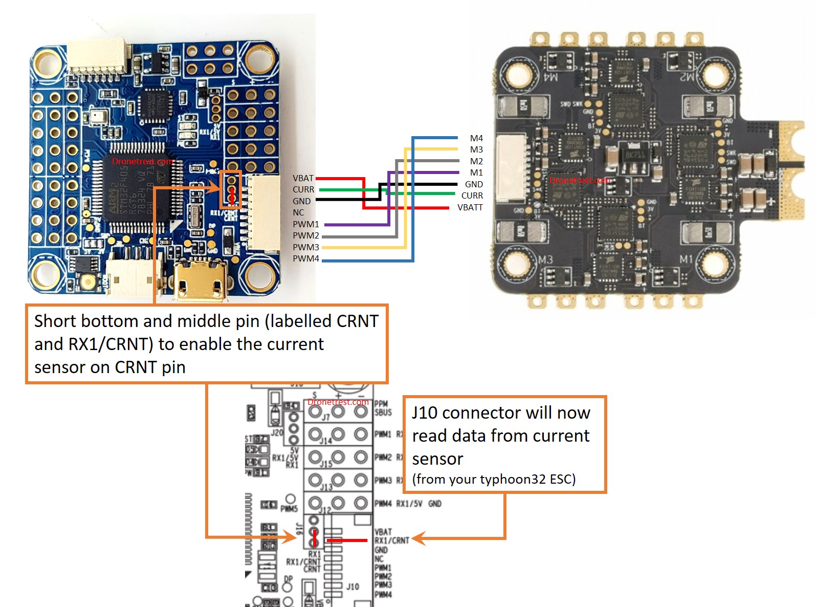
But you have an error (I believe) in the Blog. You had written it’s a JST-JH on the Typhoon 4in1 ESC. I’m sure it’s a JST-SH. As JST’s JH line of connectors looks to be old old school LPT printer ports. Also the Pin diagram is a bit off as well Since the Typhoon’s have 8pin connector with only 7 pins in use. Or at least that is what I’m trying to validate on either end of the cable. I believe Pin5 is not used.
So on the ESC side, it goes from Pin:connection
1:M4
2:M3
3:M2
4:M1
5:NC
6:GND
7:Curr (1.1) ESC_TLM (2.1)
8: Vbat
Can you or anyone confirm this? Thanks for everything. Very great writeup.
I can’t take this ish no more!!! I am on my 2nd Omnibus f4 v5 and it won’t power up like the first one and I don’t know fcking why:angry:. I love this hobby yet this board is making me want to sell all my stuff and quit. Ok, I got clean 5v power coming from my matek PDB going to the VBAT and Ground like the instructions say and like I was told by TBS and I’m not getting power to this Mutha******. Please someone help me!
HI , it states for Smart Audio “The VTX will simply connect to the spare UART1 TX port” but isn’t that occupied by Spektrum satellite connector on J8 (corresponds to UART1) ?
then I can’t find Mach2 VTX? do I just hit and miss it?
I’ve just read through the blog… I think UART1 TX is a typo and it should read…
The VTX will simply connect to a spare UART TX port and you need to enable the appropriate telemetry protocol on the ports tab within betaflight. For more information check out our VTX telemetry guide.


 Also the Pin diagram is a bit off as well Since the Typhoon’s have 8pin connector with only 7 pins in use. Or at least that is what I’m trying to validate on either end of the cable. I believe Pin5 is not used.
 . I love this hobby yet this board is making me want to sell all my stuff and quit. Ok, I got clean 5v power coming from my matek PDB going to the VBAT and Ground like the instructions say and like I was told by TBS and I’m not getting power to this Mutha******. Please someone help me!