Hi all
Got a bit of an odd problem with my MiniOSD I need some help or advice with
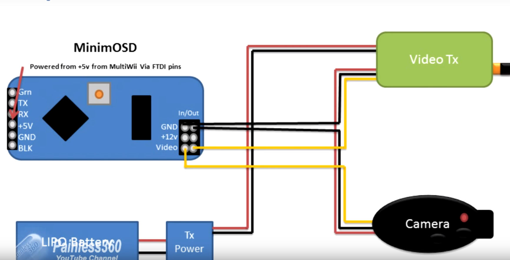
Whilst still awaiting the delivery of the restot of my FPV kit to arrive I started having a play configuring my MiniOSD ready for connection of the rest of the kit. I had watched a number of the usual YouTube videos as a guide so I was ready to connect, it was then that I noticed an odd problem, all the guides I have read or seen talk about the MiniOSD needing a 12v supply for the camera and analogue side of the MiniOSD and 5v needed for the digital side of the MiniOSD. and talk about the 12v being supplied via a battery and the 5v being supplied by the flight controller, which in my case is a pixhawk.
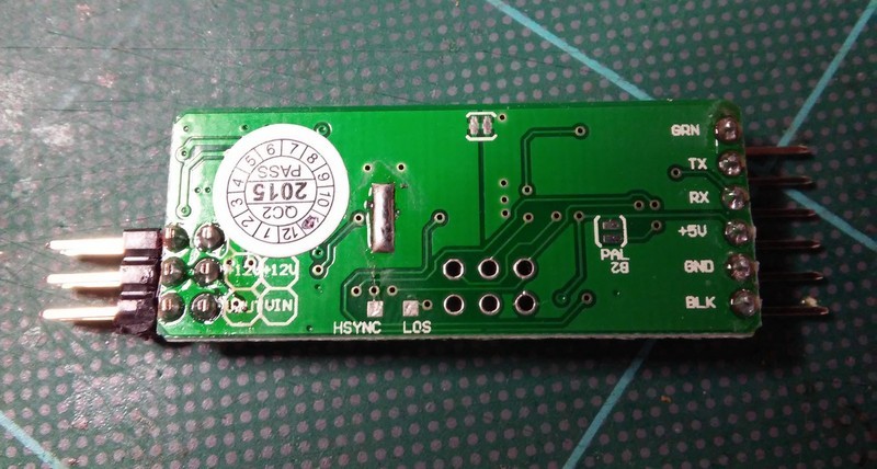
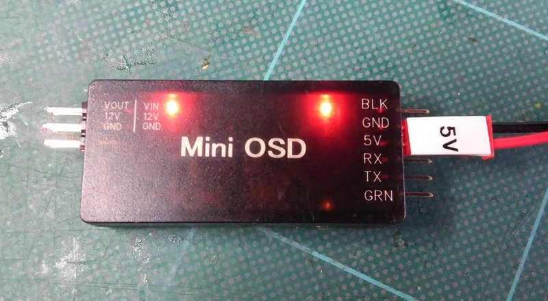
On the MiniOSD there are 2 red LED’s that light to indicate when each side is being powered. I did check and both the solder pads on the MiniOSD are not bridged
Now to my problem if I connect either the 5v or the 12v supply both LED’s light up. does that mean I dont need to supply both 12 & 5 volts to the board.
With 5v connected 5v is present on the camera 12v pin
With 12v connected 5v is present on the 5v pin
Help I am confused.
Paul
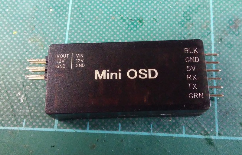
Mini OSD
12v Supplied
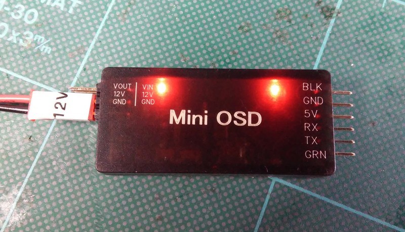
5v supplied
Board side A
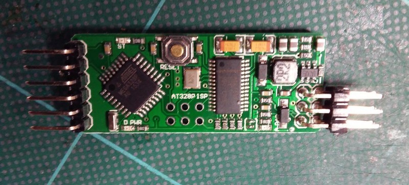
Board side B
To be honest I always solder the power jumper blobs on the top and bottom of the board to connect both 5V circuits, so that the Atmel chip and hte OSD chip share power and ground. This is because there has been lots of problems with the minimOSD voltage regulator failing, and you never know. Although this has been improved with newer revisions I still prefer to not use it as you dont want your video feed failing mid flight!.
With the two blobs soldered your OSD will be powered from your flight controller (or via some other 5V input). And then you will only connect the ground and signal wires to your FPV gear, as you FPV gear will run on a separate power system.
Hope that helps, if you need me to label the jumpers you need to solder please let me know.
Hi
Thanks for the reply
The problem is that although I do not have the tabs connected both LED’s illuminate when I connect either 5v or 12v which I understand the 2 LED’s are showing both Digital and Analogue sides are being powered, which without the solder blobs that should not be happening.
Or have I read the instructions wrong about what the 2 LED’s are indicating. Although watching videos on YouTube they do clearly show only one LED illuminating when only one of the voltages are connected before the tabs are soldered.
Still awaiting the delivery of the rest of the gear so cannot test for sure until then.
Paul
Whilst on the subject, why is it always shown that a 3cell battery is used to supply the 12v to the camera, is there any reason why its not taken for example from the 12v tap on the PDB