i bought the pixhack there was no intructions got opposite answers to a question. so here we go for the third time: I bought the pixhack complete kit the pic showed a usb port module I was told they are both the same and have usb plugs in them ten minites later got a text over the home phone to say it dosnt come with module?? i pid for a full auto pilot with telemetry so can monitor what the plane doing on its wayward points can someone explain if this pixhack 2 kit is right and if so anyone got a proper diagram on how to connect the whole thing together to my reciver
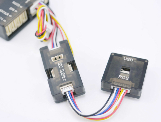
Sorry about any confusion. The Pixhack kit does not come with a USB cable, or a separate external USB extension. It does however include external LED and USB module which connects to the I2C splitter and the extension ports as shown in the image below.
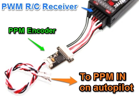
If you can let me know what R/C receiver you are using I can offer some help on how to get it connected to the pixhack. However if your receiver has PPM or SBUS out, then you can plug it directly into the PPM port of the pixhack. Otherwise if your R/C receiver outputs PWM you will need to use the included PWM to PPM encoder as shown below:
http://www.dronetrest.com/uploads/db5290/original/2X/7/7570a707df878c14aae344b8a9a8dd3d4bccc562.jpg
whats wrong with this world : I asked on a diagram on how to put it all together so far got no results emailed tried to call waste of time all I want is some instruction on how to set it up out the box so far I got gryo in gps hole buzzer in safety , splitter in serial 4/5battery into power … then come to stand still the osd and the telemetry havnt got clue where that goes by the setup on the site it goes same side as all the parts I already described plus got spare wires with no clue on what they go to : so if there is someone that has had one of these before and has got it sorted instead of sending it back please send a diagram of exact wireing please cos I ask but might as well talk to a brick wall : hope in future that the seller put clear intructions out with these kits at the moment its the worst service I ever had to encounter
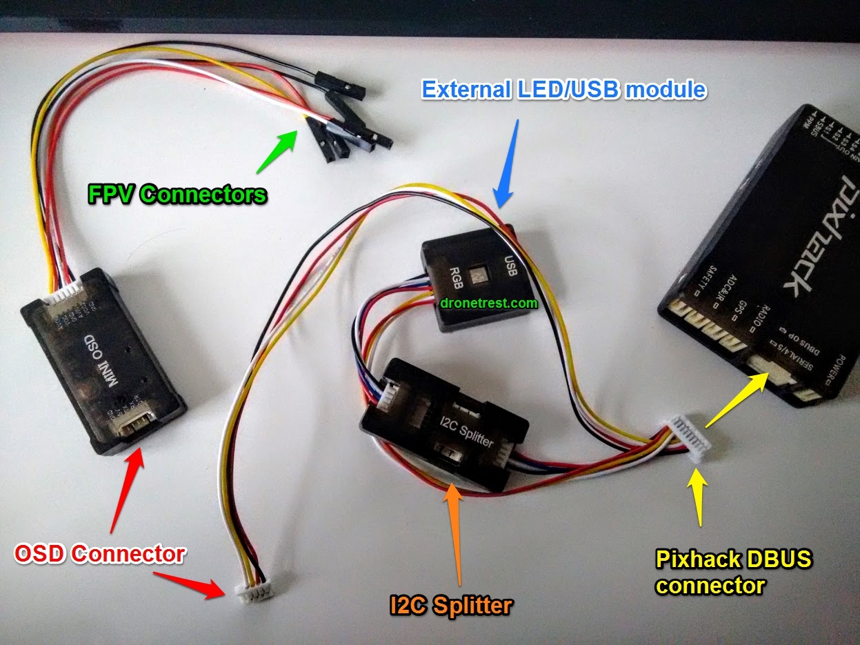
We have a photo showing how everything is connected on our pixhack quickstart guide - including full diagrams of the pin mapping on the pixhawk. If there is something that is not clear just let me know and I will try to explain it and send extra photos.
In the case of the OSD, the calbe included in the pack with the I2C splitter and LED module as the wire has an extra 4 pin connector coming out of it which you need to plug into your OSD module:
If you have any other questions let me know and I will be happy to help explain things…
And a specifc diagram for the OSD showing how to connect your FPV gear is which is also included on our pixhack quickstart guide, but I will include it below for clarity:
right there big problem with the pixhack auto pilpot the conector for the module dosnt fit anwhere in to the pixhawk box after asking several times can I have a diagram of the whole set up in detail before I send it back anyone wanting to buy an auto pilot go somewhere else and prefebly with instructions finding unmanned very unhelpful
@ghost what connector are you talking about? Its abit hard to answer a that question since there are many connectors and cables on the pixhack kit. I provided diagrams for the OSD and LED module above as you asked so I am not sure what the problem is. Could you please explain what the issue is and possibly include a photo or two so we can help you out.
Here is a detailed diagram showing all of the parts connected are on the pixhack quickstart guide post as I mentioned above but here is the image again:
What specific connector are you trying to connect and I will be happy to show you how to connect it.
Can someone kindly teach me how to connect servos to the s1-s8 channels of Pixhack V3? I’ve tried s1-Aileron, s2-Elevator, s3-Motor, s4-Rudder settings for a fixed-wing, but that works very weird. Thanks in advance.