The OZE32 AIO is a fligth controller based on the Naze 32 platform, but packs a bunch of extra features such as an integrated OSD, current and voltage sensor, voltage regulator and a PDB. All those features packed into a 35x35mm board that its the same size as the original naze 32 ![]() … If you want you can even add a GPS module too.
… If you want you can even add a GPS module too.
However all these features packed into a tiny board do make it abit more difficult to work with. For starters since the OSD and Flight Controller share a usb port, you need to change the DIP switches in order to access each one. However once you have everything setup and soldered it works great and saves a bunch of space and weight making it a great option to control your miniquad. Especially if its one of the smaller 150 size micro quads.
OZE32 Board Overview
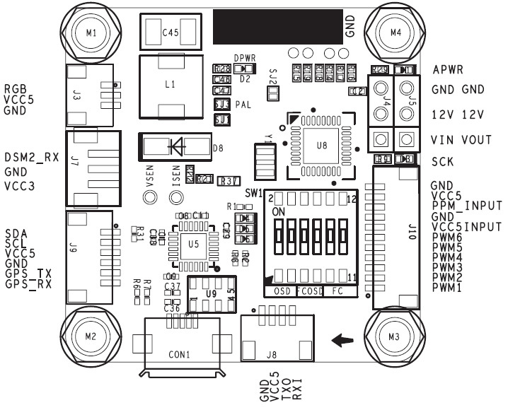
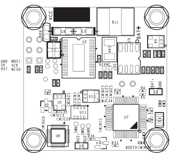
The diagrams below show the pinout connectors for your flight controller
Top
Bottom
Voltage Regulator
The voltage regulator included on the board can support up to 28V, so that means that you can use a Lipo upto 6S, although I am not sure why you would need to do this on a miniquad ![]() . But the nice thing is that this will step down the voltage to output a nice clean 5V supply.
. But the nice thing is that this will step down the voltage to output a nice clean 5V supply.
USB drivers
In most cases you should be able to connect this board via USB to your PC and it should detect it, however if not you will need to download the CP2102 USB driver from the silabs website.
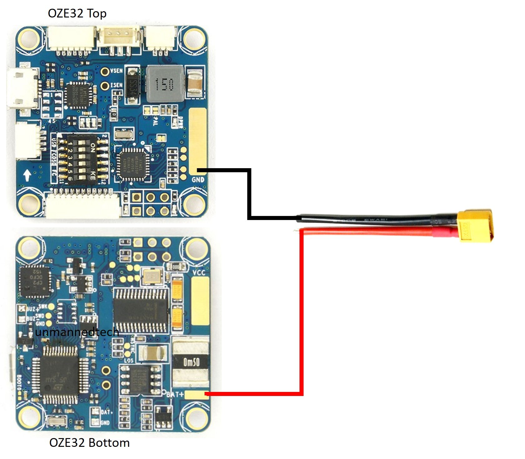
How to connect your battery connector
Because of the current and voltage sensor built into the OZE 32 you need to connect the positive wire from your battery connector to the BAT+ pad on the bottom of the board. The ground from your battery can be soldered directly to the large GND pad on the top of the board.
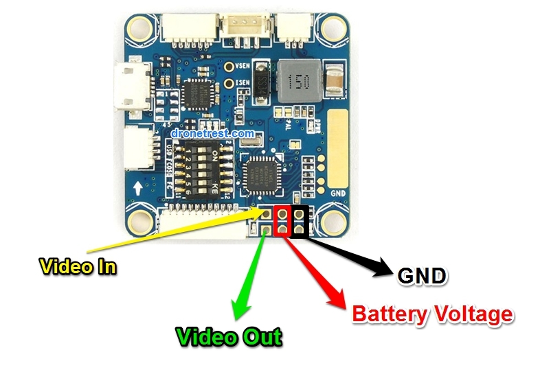
Connecting your FPV camera
On the board you will see a series of 6 pins that are used for your FPV gear. There is a video input pin that you need to connect your FPV camera to. The video output includes the OSD information and will plug into your FPV transmitter. Although there is a 12V pin, this is actualy directly linked to your battery, so its not regulated in anyway. If you are using a 3S battery this output will be close to 12V. But just make sure that the video transmitter or camera you connect to these pins are able to support the voltage of your battery. Alternatively if you are using a fatshark camera that runs on 5V, you can also power your camera from one of hte VCC5 pins on the serial ports.
Connecting your R/C Receiver
You can only use a PPM input on the OZE 32 which plugs into the PPM_Input pin on the J10 connector which also shares your ESC outputs on the other pins. A cable harness is included. A great reciever to use with this flight controller is the FrSky D4R-ii.
What about a PWM receiver?
You will need to use a PPM encoder if you want to use your PWM receiver with this flight controller
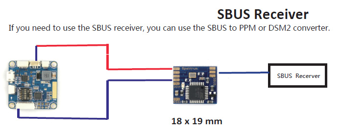
What about a SBUS receiver?
The OZE32 does not support SBUS natively due to the small size. However if you need to use an SBUS receiver you can always connect it via a SBUS to PPM converter.
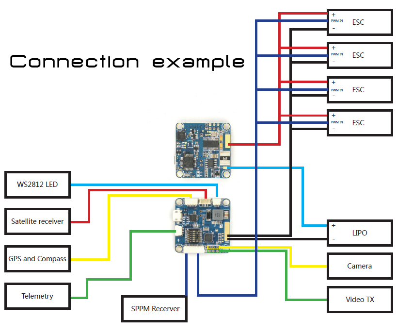
Connecting your ESC’s and other gear.
This diagram below shows you how you can solder all of your ESC’s to the large ground and VCC plates on the top and bottom of the flight controller, which is great as it means you dont need to use a separate PDB. However if you are using your own PDB, simply solder two wires from the VCC of the OZE32 to the VCC on your PCB, and similarly solder a wire from the ground of the OZE32 to the ground plane on your frame PCB.
Connecting a buzzer
A buzzer can be connected to the two small buzzer pins located on the top
Using the DIP switches
Due to the small size the flight controller only includes a single USB connector, so in order to change settings via cleanflight, or to change settings on your OSD you will need to change the jumper configuration on the DIP switch as shown on the diagram below…
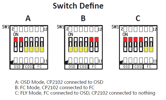
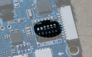
UPDATE: the manual for the fly mode seems to be wrong as it is mirrored. Starting from left to right, the first two need to be set to the off position, and the rest should be set to on as shown below:
 thanks to
Tip: If you leave your DIP switches set to flight mode and you only power your board via USB (so that minumOSD is not on) you can still connect to your FC via cleanflight, which makes things easy if you need to change some settings quickly and dont want to change the DIP switch.
UART1
The UART1 is shared by the flight controller, USB port and MinimOSD depending on how you have set the DIP switches. So unless you are not going to be using your MinimOSD there is no real point to have these pins broken out onto the J8 connector, because why would you buy this board if you dont want to use OSD?
UART2
UART2 is shared between teh DSM2_RX pin on J7 and the GPS pins on J9 where the pin labeled GPS_TX is UART2_TX and GPS_RX is the UART2_RX pins. If you are not going to be connecting a GPS/Compass module to your OZE32 then you can use the UART2 to connect an openlog blackbox unit, or a bluetooth mode to enable wireless communications with cleanflight (no need for a USB cable!).
However if you are using a Spektrum DSM receuver with this you will not be able to use the UART2 for anything else.
Updating OSD firmware or changing settings
Please note that the USB does not provide power to the OSD, so whenever you are updating firmware, or want to change settings on your OSD you will need to plug in your flight battery to power it.