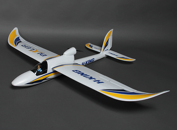
Dave has shared a great build log of the Bixler, which is a great plane for a UAV platform. Its not the biggest, but its great to fly and cheap enough to replace if you need too.
The purpose of his build log is to allow for a reliable, high performing Bixler drone on a budget.
Bixler Equimpent List
- Bixler 1.1 ARF
- Motor
- ESC
- SBEC (Optional)
- ESC Programmer
- Motor mount (for spinning bigger props)
- APM 2.6 with separate GPS/compass
- Radio: Spektrum DX8
- Receiver: AR6210, no satellite
- Prop: APC 7-5. The HK 7-5 prop came with horrible adapter collars and I do not recommend them!
- 30cm 4 position cable
- 30cm 6 position cable
- 5 pin housing
- Female-female jumpers (15cm x 7 qty)
About using an external SBEC: I chose to do this because I am an RC heli guy, and I am used to using servos that draw ridiculous current. My thoughts are that if you supply the servos separate from the motor, there is less chance of either one shutting down due to over-current draw (but you also add a second electronic device that can fail). I am thinking of when the motor is at max throttle and the servos are fully deflected, such as on a very windy day, the separate BEC will give you some headroom. If space becomes an issue, you can always get rid of the external BEC and use the internal BEC from the ESC.
Programming the ESC
Set up the programmer card as shown in the image below
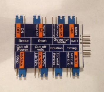
- Set the low voltage cutoff to its lowest setting to allow the APM failsafe feature do its job.
- Don’t worry about FWD vs REV; you can just switch two of the motor wires if the motor spins backwards.
- Connect the ESC to the card and the motor (no prop).
- Plug the ESC into a battery and you should get one tone from the motor, letting you know that programming is complete.
- Disconnect the programming card and then the battery.
Connecting the ESC and BEC
I chose to use EC3 connectors in my build, because all of my batteries have them. XT-60/Deans are also fine.
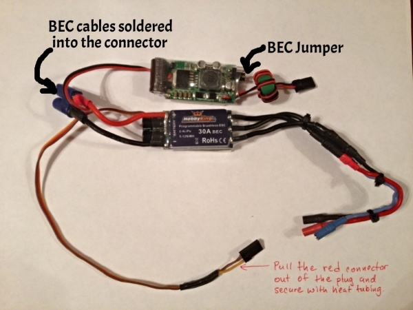
- Cut the servo power lead off of the BEC at the connector. Solder the BEC power cables with the ESC power cables into your connector. This can be a little tricky, but if you get the solder hot in the connector, you should be able to slip the BEC power cables into the connector after you solder the ESC cables. Just keep the heat on it and slip them in. It helps to have a set of “helping hands”, but I use my children instead

- I chose to run my servos at 5V from the BEC. There is a jumper on the end of it that lets you select 5 or 6 V. Before I reinstall the electronics I will secure the jumper on the BEC with a glob of hot glue or shoe goo.
- Pull the center (red) pin and wire from the ESC receiver connector. This disconnects the built in BEC from the ESC. You don’t need it, it is only powering the motor. Make sure to tuck it away with heat shrink tubing. You will need it if you need to re-program the ESC.
Mounting and Conneting ArduPilot Mega
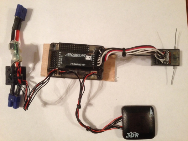
- Make a 45 x 100 mm mounting plate for the APM using 5mm plywood (or plastic or fiberglass board).
- Use a 1″ square of Kyosho Zeal Gel or Dubro foam under each corner of the flight controller to provide vibration suppression. Zeal has high strength double sided adhesive, but if your pads do not, consider using “Welders Glue” (for more information see the vibration damping post.
- Welder’s Glue: it is contact cement. Lightly cover each surface you wish to bond and let them dry for about five minutes.
- Then carefully align and put the two surfaces together and for immediate bonding.
- I will also use Welder’s Glue for assembling the foam air frame and building an access door in the fuselage.
Preparing the Bixler Fuselage
- The APM is mounted inverted and we want to get it level with the fuselage (level with the line of flight).
- You can see that the wing has a positive angle of attack when the APM is level.
- If you just stick the APM to the bottom or top of the fuselage it will not be level, which may affect performance.
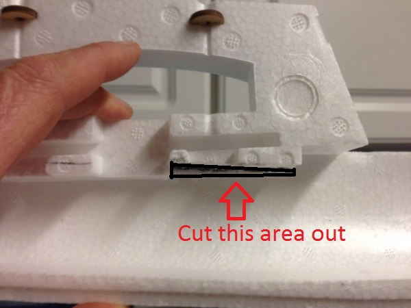
- I don’t like to take chances, so, I removed some of the foam below the top inside of the fuselage to get the APM level:
Mounting the APM into the Bixler
Here is the APM set in place with some of the components. At this point you want to mark where your access panel will be.
Trimming the Bixler Fuselage
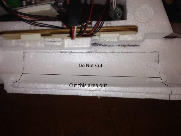
I originally cut too much and the fuselage was really weak. No problem; with some hot glue you can easily fix any boo-boos.
- In the picture above you want to cut the lower portion and leave the area I have labeled “Do Not Cut”.
- You will have ample room to access the APM Inputs and Outputs, as well as the USB port and other pins.
- Cut straight through the foam so that the panel will open easily.
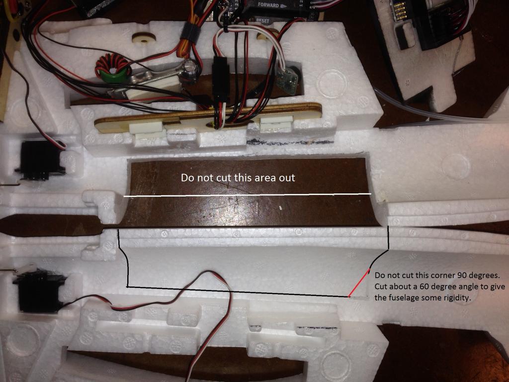
- Now match up the two halves to mark the cuts for the right side.
- Cut a larger access panel out of the other (right) half of the bixler fuselage so you can access the USB port on the APM.
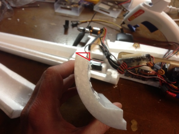
- Now you will need to cut a bevel along the long axis of the large panel we already cut out.
- I think that my picture is incorrect above; make this cut on the panel from the right half of the fuselage.
- This is not the edge where the two halves of the fuselage join, but the cut near the wing.
- Now, make a Welder’s glue hinge where the bevel (that we just cut) meets the fuselage.
- This creates a hinge for the panel that is invisible and super cool.
- Don’t worry, custom foamies use this type of hinge for hundreds of flights.
- Here is link to a YouTube video explaining how to make a Welder’s hinge:

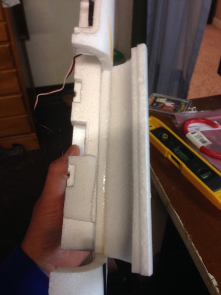
The panel should look like photo above when the Welder’s hinge is complete.
Assemble the Bixler Fuselage
- Follow the Bixler instructions and glue the halves of the fuselage together.
- Again, I use Welder’s glue, applying a thin bead to each half, letting them get tacky, and then assembling the halves.
- Run the motor cables from the ESC to the motor before you assemble the two halves.
- No worries if you don’t, but it will save you the trouble of trying to attach the motor leads with needle nose pliers and hemostats.
- You should also check the rotation of the motor so that you do not have to switch motor leads for a motor spinning in reverse.
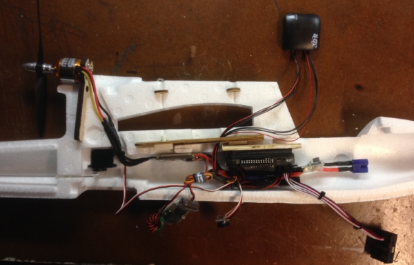
Component Installation Details
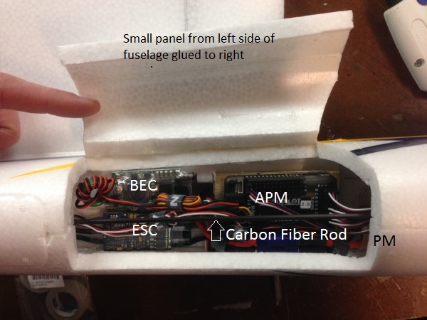
- As shown in the picture above, I have the fuselage glued together and the components glued in place.
- I like hot glue for this detail.
- Notice that I glued a 3mm carbon fiber rod across the access hatch for added rigidity.
- At this point you will notice that space is becoming sparse
- You will notice that we have put nothing in the nose so far, and all of our components are pretty tightly tucked under the wing. I did this so that we can utilize bigger batteries in future builds.
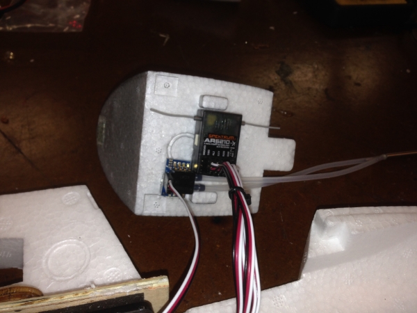
- This time around I am using an airspeed sensor which is recommended, but not necessary if you are on a first-time build budget.
- To make space for batteries, I mounted the airspeed sensor board and receiver to the bottom of the canopy hatch:
Finishing Off
- Use a servo splitter cable for the ailerons, I got odd results when programming separate aileron servo on its own channel.
- I am quite happy with this setup because you can get the CG perfect with Zippy 2200mAh Lipo batteries.
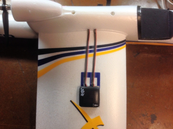
- I mounted the GPS/Compass on the right wing after removing just a small amount of material.
- I mounted it with hot glue and taped the cables in place with 3M Blenderm tape.
- I like Blenderm because it sticks well and is flexible.
- Having it sitting up high on the wing is not ideal, but I wanted to get it away from the fuselage and all of the current-carrying electronics.
Thanks to Dave Smith for the build information, more to come soon like setting up APM etc…