APM 2.8 installation questions!

A newby here: I’m trying to get a hex flying - replacing a faulty APM 2.5 (with what I believe is a faulty compass on-board. See * below.) with an APM 2.8 Arducopter, 3DR GPS, (supposedly with a Ublox Neo-6M mag compass on-board), using Mission Planner 3.2.1.

  • Everything works fine with the old APM 2.5 except the compass reverses east and west (when the 'copter is physically pointing east MP shows it is pointing west.) Radio-, compass-, GPS- and ESC-calibrations all work just fine - but the compass reads east and west backwards. North and south read correctly. I have no idea what is going on with that module. Replaced it twice with (supposedly) like module - neither of them worked AT ALL…

Received a new APM 2.8 modlule, installed it, along with the 3DR GPS/Compass. Radio-calibration checks out fine. When I try to do a compass calibration I get no indication in MP that the compass is outputting any signal. Rotating it through all the axis produces no dots on the calibration screen. The red light and the blue light in the GPS module are on (blue is on steady, red is on intermittently) The blue light (GPS) on the FC is on steady, the red light flashes continuously, as do the yellow and the amber lights. I get NO indication the board is arming the ESC’s when I try to do that.

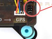
Here are some photos of the APM 2.8

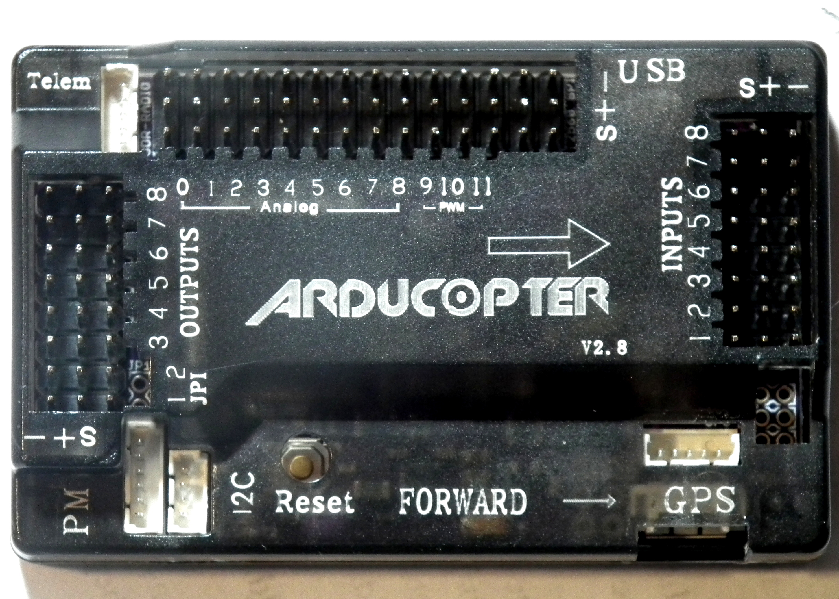
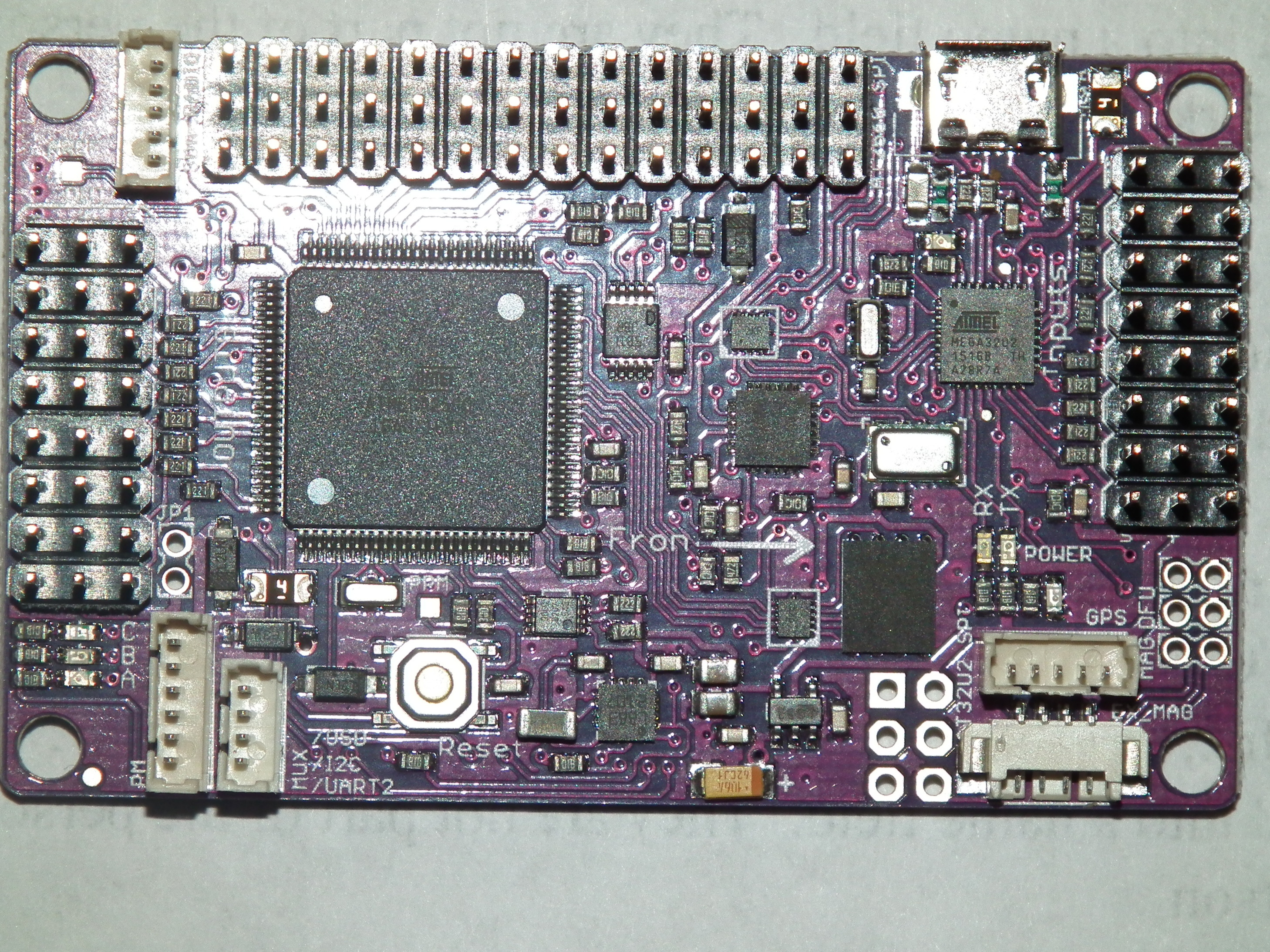
Some write-ups I have seen say the APM 2.8 DOES have a on-board compass, others say it does not. I can’t see anything that looks like a compass (like the one I can see on my old APM 2.5) but, then, I’m no electronic engineer either.

If it does have such a compass, how is it activated? (I’ve tried various combinations of “enabled”, “Not enabled” for both internal and external compasses in MP, but nothing seems to work. I have the 3DR GPS plugged into the GPS port on the top of the FC and the compass plugged into the compass port on te side, but don’t get any signal to MP when I try to do the compass calibration.

Any suggestions?

It sounds like your GPS/Compass module is the same as mine and the compass is mounted upside down on the bottom of the GPS module PCB, and will cause the same effect as you’re having.

To correct this you have to enter the Compass setup screen "Initial Setup->Mandatory Hardware->Compass"
and IIRC it’s under Compass 1 and ther’s a dropdown, (showing ROTATION_NONE), and change to “-180
degrees” (or something like it, sorry but I’m at work and going from a poor memory on the exact wording).

Mark.

EDIT: Just been researching this some more and it looks like you select “Roll-180” to correct for an upside down compass.

I can see the logic behind your suggestion - I.e., that the compass may be mounted upside down on the PCB. I hadn’t thought of that possibility, mainly because this is, in reality, a second-hand 'copter that I got from someone else, and that person assured me everything was working fine with it when I obtained it. The 'copter subsequently sustained major damage in a crash (broke three of the six motor support arms, among other things) and hasn’t flown at all after I replaced those and a few other structural parts. The APM 2.5 FC that was aboard during the crash is the one which now gives me these errors.

Just this evening I (finally) got my new APM 2.8 FC hooked up and set up in Mission Planner. Everything seems to work well with the GPS and compass on this unit, so maybe I can get a little air time with it tomorrow!

1 Like

Rats! Powered it up this morning, everything worked fine - until I tried the motors to see if they would arm and then run. Arm? - yes, they would. Run? - yes they would… sort of. All of them started at the same time with the exception of #1 - it wouldn’t run at all!

After about five minutes of trying to get #1 to start I gave up and shut everything down. Went to pick the 'copter up from the workbench and… OUCH! Burned a finger when it came in contact with the ESC of #6 motor! That puppy was HOT - and so were the ESC’s of all four other motors that had been working. The motors weren’t hot, just the ESC’s. I’ve never had that kind of trouble before.

I did have to replace the PDB on the 'copter after the disastrous crash earlier this year (the old one suffered a ground wire pull-out of the plug that goes to the FC and I cannot get it back into the male plug module. I also do not have a replacement module to swap with the old module - and, besides that, a new PDB [exactly like my old one] came with the FC package, so I put it on the 'copter in place of the old one.]

I’m suspecting the new PDB might be putting out too much voltage for the ESCs, but don’t know how to measure that voltage (I’m not much of an electronic engineer-type of hobbyist.). I do have a volt-ohm-ammeter but I just don’t know which wires to touch to get the output voltage that is going to the ESC’s.

Any ideas?

Firstly, the PDB shouldn’t be able to put out too much voltage to the ESCs, as it’s supplying battery voltage.

However, to check the ESC input voltage,

  1. Make sure the ESCs are not armed, (even better, remove the props to be on the safe side), and ensure throttle is set to off
  2. Connect the battery,
  3. Set the DVM to DC voltage, and putting the Red probe to the Red wire on the ESC, and the Black probe to the Black wire on the ESC and the DVM should tell you the voltage - it should be the same as the battery voltage.

Secondly, your HOT ESCs can be caused by several reasons, but primarily by…

When running at part throttle, the FETs are switching on/off continously, and to cut a long story short, they have to ‘dump excess energy’ and the waste energy is given off as heat. Conversely, at full throttle the FETs are ON all the time, so no ‘dumping of energy’ takes place and they run cool.

As you mentioned arlier about lengthening the ‘servo’ cable, I’d also be interested in the ‘total’ length of your battery leads, from battery, through the connector, the PDB, all the way to your ESCs?

Mark.

Abit of a delayed reply, but with the APM2.8 you need to connecth the jumper on the MAG pins to use the built in compass.

Otherwise if using an external compass you need to remove the jumper.

Hope that helps

Thanks for showing me where that jumper is. As it turns out my problem was one of the wires on the USB cable going to the FC was not making good contact in the FC socket, so that wouldn’t allow anything from the compass or the GPS to be seen by Mission Planner. A little work on that resolved the compass problem.

Thanks for helping. It’s people helping people that makes this hobby interesting to those of us who are new at it.

1 Like

Thanks for your reply about the hot ESC’s… it helped me understand how the FC controls the power the ESC’s output to the motors. It must be some kind of variable resistor system in the ESC that restricts the full battery voltage from getting to the motor, and that means the voltage that is not being used by the motor has to be converted to heat, right? Seems there ought to be a way to return it to the battery… but, then again, I’m no engineer so what do I know…

Just reviewing this thread (still having trouble getting the external compass to orient properly). I appreciated your answer as to whether or not APM 2.8 has an on-board compass. I installed a jumper in the area you circled on your illustration, using those that are nearest the white “GPS” lettering on the part. When I went to calibrate the compass there were no indications of any output from a compass, so I am thinking that (at least this) APM 2.8 does not have an onboard compass.

Good day to everybody all the way from South Africa
I am a beginner and I have decided to build an RC aeroplane and with the APM 2.8 ,yes, it is my first built plane, havent even flown it yet due to always windy days recently, and a apm 2.8 problem, but I was actually thinking of removing the apm 2.8 and flying manually just to see if the plane flies,since I have experiencing a problem as well.

Just to let you guys know, I have purchased a power module for the apm, and my esc is the Simonk 20A and it has a 5v 3A which I am not sure of but thats what is written on the product description. I have purchased a power module for the apm, and my flight controller is the flysky fs i6.
I think its a power supply problem because heres what I tried…

Without using the power module, I connected everything, which is the remote receiver and the apm and from the apm, three servos, and esc(red wire connected in the connector). JP1 jumper switch was connected, each servo using its own remote channel…

channel 1 - right side wing aileron
channel 2 - elevator
channel 3 - esc
channel 4 - left side wing aileron (used the mix function on the remote as a slave to channel 1)

I have done all the calibrations in Mission planner.
When I plug the battery on the aeroplane and turn on the remote either indoors or outdoors, everything seems to work, but, not altogether, if I use the remote control to move the servos and spin the motor at the same time, the board seems to cut out power as if a reset but with no beep, and the motor stops spinning and servos wont move until a few seconds, thats when the blue and red lights turn off but the orange/yellow stays on, then the blue and red begins to blink again and I can either spin the motor or move the servos, but never all at once, otherwise the board seems to turn off the blue and red lights, seems as if not enough power to the apm?

Then after so much of confused reading because its never perfectly explained, I connected the power module to the apm, pulled out the red wire from the esc, and pulled out jp1 jumper, and when I connected the battery to the aeroplane, the lights began to blink on the apm, and the motor works/spins when I add throttle, but servos do not work, only the motor works.
Then I added the red wire of the esc into the esc connector and tried again, the servos began to work, but, when I connect the battery to the plane, i instantly add a little throttle just to keep the motor turning, and the apm turns on, but after a few seconds, the blinking blue and red lights turn off, and another two or three seconds, they turn back on, but motor does not work anymore, when I increase throttle, it does not turn, but the servos work. I tried the arming method for the motor, but does not work.

So i was thinking of trying this… keeping the power module plugged in, keeping the esc red wire plugged in, AND inserting the JP1 jumper in, but I am afraid and need to know if I will blow the apm or can this be done ?

Update : Still thinking that it was a power supply situation that was causing the problems above, I disconnected the three servos only from the output of the apm 2.8, and the strange thing is that the symptoms are the same even though the servos are disconnected from the output , but are still left connected from the remote receiver to the apm input. Seems that the apm is causing it ? Its like the apm lets it work at first, then switches off only the blue and red lights, which then disables the motor, and then the blue and red lights blink again.

Some interesting results has occurred, i have not flown my first built rc plane as yet, however, yesterday,I tried plugging the apm into mission planner, I did so with just the esc plug… to be precise, I made the normal connection for using the apm, but only the esc.

I plugged the apm into the pc via usb, then turned on the remote and plugged the flight battery into the rc aeroplane using the power module, no jp1 connector, red wire of the esc still connected into the esc plug and in the apm channel 3, and I found the arm button in mission planner, which I clicked and armed the plane, the HUD displayed ARMED, and i turned up the throttle and it worked ! The throttle was never turned off by the apm after that, even after disconnecting the usb between pc and apm, the throttle worked, but, when I disconnected the flight battery, and tried again without the usb connection to the pc, it had the same symptom again, the motor can spin up with throttle when first plugging the flight battery in, but after a few seconds, the apm cuts out throttle only. Right now, before writing this, I connected the servos as well to the apm, connected the apm to pc mission planner, plugged in flight battery, armed the plane in mission planner, and awesome stuff, the motor and servos seem to have worked perfectly and together as well, but when disconnected from the pc, and I try plugging in the flight battery, the same problem persists. So how can arming the plane on mission planner make the plane work perfectly but does not on the plane without mission planner connected ?

When I first plugged everything in on the plane, everything worked, I did not had to arm the plane, if I plug the flight battery in, and just push the throttle, the motor will spin like normal, only recently, this problem began, and I have tried arming from what others mentioned, but none of the arming techniques worked, but somehow, mission planner arms it and everything works perfectly.


I have solved the problem, I realized that I just had to find the correct arming method for my remote to the apm, my remote is the flysky fs-i6, Mode 2, and I just found out now by experimenting, that to arm my plane, I had to move both sticks to the bottom right for several seconds, and when I turned up the throttle, the motor began to work, and with the servos. I will try to fly it today with apm connected.

It was merely a simple arming that was required, but since I never had to arm it previously, that was why I believed that something else was causing this problem and couldnt figure it out. Seems that with these electronics, they can be moody and change lol.

I hope that these posts would also help somebody else out there experiencing the same problem as well !