Arthur… all I’m getting is signal strength, battery Voltage and it talks when I Change from loiter to rth and such.
That’s the exact same thing everyone seems to be getting from this mod, including me. There are other sites reporting this, too. Have a look at Diydrones and the statements Grandpa_Jake made there. It only transmits a few bits of information from the quad to the mobile device. The other way round doesn’t seem to be possible. If I’m mistaken with this point I’d gladly hear corrections from other users including instructions how to get it done but I think it’s just not possible to transmit commands from your mobile device to the quad (ie enabling the ‘follow me’ mode).
Does not work… why would you post such nonsense unmanned tech.
1 Like
The basic telemetry is being transmitted but no upload is possible with the current modification (I did not change the resistor but I would like to know if anyone had any success by doing this). The connection is obtained using Ctrl + T. As Grandpa_Jake said in another forum, you can program the Quad using the USB connection and, after, have the radio to know what the quad is doing. That’s fine for me too. Today, with some new info from 3DR v2 original radios, I was able to connect them to the Walkera X350 Pro, using SIK 1.9. Work just as the V1. These new radios are great because you have USB ports in both. This will skip the need for FDTI connectors to tune the air radio.
Please, if someone solve the improved download and upload connection please share.
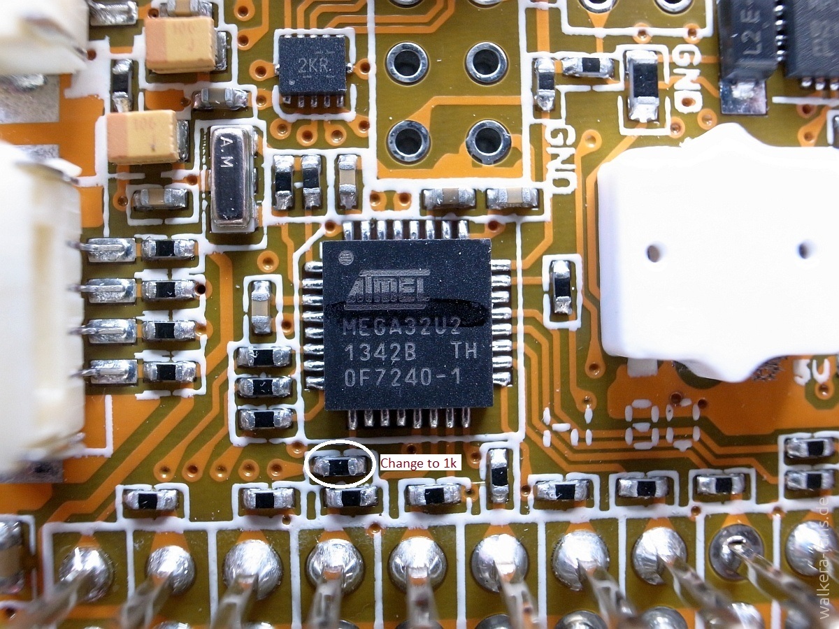
I am looking into this as it seems that many of you guys are having an issue, there seems to be some problem with using the 3DR telemetry modules. I initially tested with a bluetooth module and assumed it would work fine with the telemetry module but since the TX line is closely coupled with the ATmega chip at 5V so it makes it hard to communicate since the 3DR modules have a serial interface of 3.3V so you will need to add a 680ohm resistor as shown. I will update the first post with more details along with links on where to buy resistors soon.
I add a 680 Ohm resistor like it is shown on the picture, but it didn’t work. The result was the same with 680ohms or with original ( 220 Ohm resistor ). Just couple of parameters like battery and switch position on the radio ( simple mode, position mode or RTL ), that is all ! CTR+T just do the quick connect and nothing else.
Hi resmanm. I regret a lot that you were not able to get the data flow correctly after changing the resistor. I hope that unmannedtech and others, with more electronic knowledge than me, can figure out a solution. However, as a matter of fact, you can get a lot more with this setup, like GPS update position and IMU data, but with a small trick. If you connect directly with the radio you will get only the parameters you told. Try to do as follow: Get the quad and the RC radio connected and binded. The telemetry radio must already be connected to the computer and also online with the “Air” part. If you have GPS fix it’s even better. Connect the USB cable to the computer. You must have, in mission planner, both the quad and the telemetry radio available in the “port” list. Connect to mission planner via USB. The mavlink connection goes as expected. You should be able to see the telemetry flow correctly and upload missions and parameters. After, just disconnect the USB cable, go to the port list, get the telemetry radio port and hit Ctrl + T. You will see that the telemetry (including GPS data and IMU data) continues to update perfectly. You can not upload anything but, at least you will know everything that the drone is doing, unless you loose radio signal. It’s not the most appropriate way of doing this but I’m satisfied. Of course, it will be better if we can get full duplex communication.
Thanks a lot Rhenriques. I will try this, but like you say, if we can get full duplex that would be the best 
@Rhenriques, you also need to change a resistors on the other side of the board next to the ATmega chip. As I mentioned I tried the 2 way telemetry with a bluetooth module and assumed it would work with telemetry modules without the resistors. The actual photo of the telemetry module is from our CX-20. When I get a chance I will update the guide to give full details and find correct resistors values (if possible) to use the 3DR telemetry radios.
Thank you so much unmannedtech. If possible give us the specifications of those resistors (part number for instance). I have a microelectronics store near me but the smallest resistor they could get me is about 5 times the size of these ones.
Is it possible to have some tolerance in these values? For instance use a 560 ohm instead of a 680 ohm one? My seller had the first and didn’t have the second.
Since the voltages between the devo and the module are not the same couldn’t we use something like this ?a bidirectional voltage regulator
Fanisanagn, that seems to be a very nice idea!! I can be saying something wrong but isn’t this the purpose of changing the resistors? After all the objective is to convert a 5v signal to a 3.3v one. And that could also avoid accidents while soldering very small resistors into DEVO-M.
Maybe this one works too. It’s cheaper.
I’ve ordered two different bidirectional voltage regulators. They will take some time to arrive. I’ll test them and let you know the results. It would be great if these could skip the need for resistors exchange. Some Arduino based sensors only work correctly with these 5V-3V signal converters. Maybe this can make the mavlink connection to DEVO-M full operational.
*DO NOT TRY THIS AT HOME *
YOU WILL BE ORDERING A NEW DEVO M
The only reason someone goes through all this trouble is for the follow mode which is not obtainable.
FOLLOW MODE DOESN’T WORK
Repeat this is all B.S.
Wrong Zane, this is not for the “Follow me mode”, at least in my case. Telemetry is already working good from the Walkera X350 Pro to the ground with unmannedtech’s instructions and adds from this forum. The advantage of having full connection is that you can control or plan missions to your Quad with an android plattform or with a computer, via mission planner, and control everything from the ground in real time. If you need to do aerial surveys for photogrammetry, you will notice how important is to have this full duplex connection.
Please Unmannedtech, avoid this 3 posts limit. Probably, this little thread is the most useful that I saw until now to add telemetry to the Walkera X350 pro. You are serving an important aid to the owners of this product!!
WARNING
*DO NOT TRY THIS AT HOME *
YOU WILL BE ORDERING A NEW DEVO M
The only reason someone goes through all this trouble is for the follow mode which is not obtainable.
FOLLOW MODE DOESN’T WORK
Repeat this is all B.S.
I WISH SOMEONE WOULD HAVE TOLD ME THIS!
1 Like
PLEASE NOTE ALSO THAT THE SCHEMATIC DIAGRAM IS INCORRECT!
Here is the comparison:

Please can someone confirm this mod is working and that I can get Telemetry on my walkera x350 pro? I’m not bothered about the follow me function.
And would anyone be willing to do the solder work for me? Thanks
Just to let everyone know, I am working on updating this guide to include everything you need to know, I am investigating an alternative method that does not require you to change any of the resistors so please hang tight until I update the post with full details.
2 Likes
That’s awesome! I hope that you managed to achieve that with the voltage converters. I’ll be paying attention to your update. That will be a great milestone to the Walkera X350 pro users. Thanks for all your effort
Rhenriques
1 Like